When looking for a low frequency RFID emulator for security testing purposes, you can find several designs out there. However, their complexity can make you think twice before building one.
Is necessary that complexity? In some cases you don't need too much functionality. Just a simple RFID emulator without fancy capabilities.
How simple can be an emulator? Let's see.
The simplest possible RFID emulator
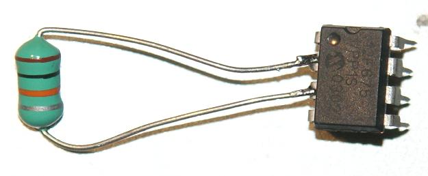
Look this!
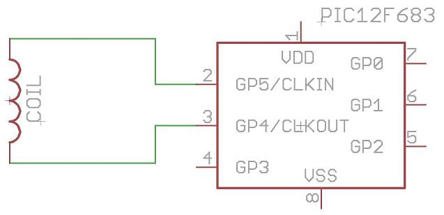
And this is the schematic:
Can something this simple works? Check this video. It emulates a EM4100 tag.
HOW IT WORKS?
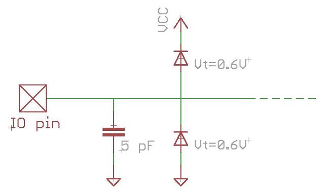
In order to understand how this simple design on PIC12F683 can works, we have to consider the internal connections of the microcontroller IO ports. Consulting the datasheet, we can observe that every IO pin has an internal parasite capacitor (around 5pF) and a pair of clamping diodes, as this diagram shows:
Considering internal capacitance and diodes, the result schematic of this simple emulator is something like:
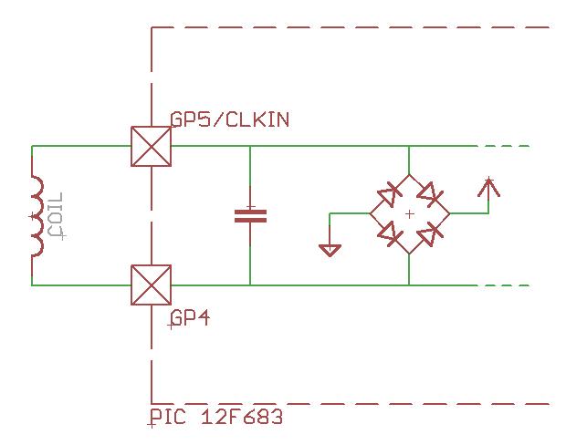
The parasite capacitor in the IO pins and the external coil form a LC resonant circuit and act as an antenna. This antenna will pick up the carrier generated by the RFID reader. The recovered carrier is rectified thanks to the bridge formed with the clamping diodes, feeding back the result signal to the power supply of the microcontroller.
Note that the coil (antenna) is connected to the GP5 / CLKIN / OSC1 port. This is important, but we will back to it later.
The other terminal of the coil is connected to the GP4 port. In order to transmit data to the RFID reader, we have to modulate the low frequency carrier by changing the coupling between the reader and tag antennas. We can achieve this by switching the GP4 as input (High-Impedance) or output (connected to GND).
THE FIRMWARE
Some knowledge on PIC assembler is requiered to understand perfectly this section.
Basically, The code for emulating a read-only tag is not more than a bunch of "well-timed" instructions that modify the GP4 state. This microcontroller (like most of the modern PIC microcontrollers) has an internal oscillator. However, instead of using the internal oscillator, the firmware uses the RFID carrier, present in the GP5 pin, as the system clock.
This way, the firmware is simpler because there is no need to synchronize the data modulation (switching the GP4 pin to GND or High-Impedance) with the RFID carrier. The code execution is already synchronized with the carrier. The oscillator block has a "relatively" high power consumption, so another reason for not using the internal oscillator is to save energy. And less power means longer reading distance.
The EM4100 is a read-only tag with 64 bits of memory and is usually found configured to work at 64 clocks per bit and with Manchester encoding. The Manchester encoding implies that a '1' encoded bit is transmitted "half-bit" (32 clocks) as '0' and "half-bit" (32 clocks) as a '1'.
As firmware example, you can download this ASM source. It emulates a EM4100 RFID tag.
Part 2 - Improving the emulator