Part 1 – Description and Schematic
Part 2 – Firmware and Sowtware
Assembly
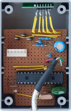
Because the circuit was so simple I took the easy way out and assembled it on a piece of veroboard. Nowadays I would design my own printed circuit board (see custom PCBs).
Rather than finding a connector for the Cypress module I simply soldered single core hookup wire directly to the connector pins. This supported the module and allowed me to position it away from the microcontroller to minimise interference.
The USB cable was made from a standard USB cable with type A and B connectors, I just cut off the B connector and soldered the wires directly to the veroboard with half an inch of heatshrink tubing to keep it neat. That left the type A connector at the other end, ready to plug into the computer.
Note that the red and black wires in the USB cable are +5V and ground respectively. You should check these with a multimeter before soldering them in. The green wire is normally D+ and goes to pin 16 of the 18F2550 while the white is D- and goes to pin 15. The shield does not have to be connected.
The final touch was to drop the assembly into a standard UB5 "jiffy" box with a notch cut out for the USB cable to pass through.
Using the Scanner
With nothing running in the immediate vicinity you will just see background noise, as shown in the screen shot below.
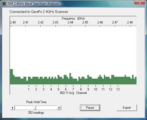
Note that the vertical scale is not calibrated to any particular scale. In fact the scale is just the signal level "factor" reported by the Cypress radio module.
The base level signal represents the noise in the air and in the radio receiver part of the module.
The screenshot below shows a WiFi 802.11n wireless router running on channel 1 and located about 12 metres from the scanner. As you can see the 802.11n (and for that matter 802.11g) routers spread themselves over six channels.
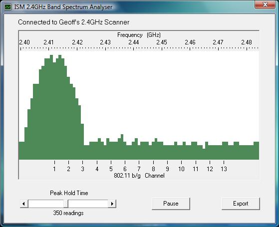
That is the good thing about using channel 1 and 13 for your WiFi setup, you get some unused channels on one side where your spectrum can spread into.
But, using channel 13 has its own problems.
The spectrum on the next screenshot is identical to the one above but this time my microwave oven was heating up dinner. Incidentally, the microwave oven was nothing special, just a domestic model and about 10 metres from the scanner.
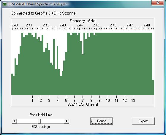
As you can see, it totally blotted out the higher frequency end of the band. All microwave ovens seem to use this part of the band and you cannot blame the microwave for their activity, as this was part of the reason for setting up the 2.4GHz ISM band in the first place. Avoiding the microwave oven interference and having some free spectrum on one side is the reason why channel 1 is the best choice for your router (assuming your neighbour has not got there first).
Finally, the screenshot shows a Bluetooth mouse communicating with a computer.
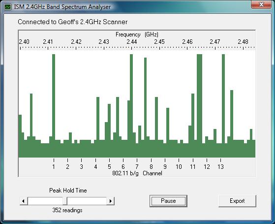
Bluetooth hops all over the 2.4GHz band as it finds the best spots with the minimum of interference. Spikes all over the spectrum is a good indicator of Bluetooth activity.