Signal amplitude gain control
After we have adjusted signal offset voltage filtered it (or not) the next part is to adjust amplitude. We need to adjust signal amplitude from 0 to 12V. For this purpose we are gonna use inverting amplifier with potentiometer adjustable gain. Wee need to calculate proper resistor values to get nice gain control over all potentiometer turn. Say we are going to use 47k potentiometer. Lets calculate input resistor value.
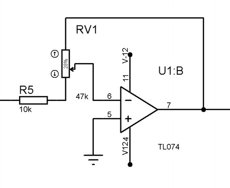
Another known condition is that input voltage from previous stage is 2.5V. Say we want to get 12V amplitude on output we need gain: 12/2.5 = 4.8. If we turn potentiometer to the max left we get:
R1=47k/4.8=9.79k~10k. In order to get 0V amplitude we just need to turn potentiometer to the right so gain ration gets close to 0.
Signal offset regulation
And last stage of analog part is signal offset regulation. We want to regulate offset in range of -12V to 12V. The easiest way to do so is to add offset voltage to signal voltage.
Since we already have two inverting cascades we don’t want the last one to be inverted that would lead to inverted signal on output. So we are going to implement non inverting summing:
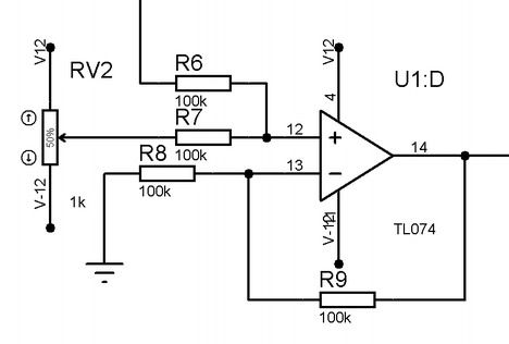
Lets see how to calculate resistor values. R6 and R7 we select to be 100k resistors as they aren’t critical while in recommended range 1k to 1M. More interesting part is gain. Lets see how non inverting summing amplifier output voltage look like:

What we see here is a voltages added and multiplied by gain. Since our R7 and R8 are equal to 100k we get that only half of these voltages are added. So we need to adjust amplifier gain to 2 in order to operate with full values. So we need:

after solving we get that both resistors have to be equal. In order to keep resistor values less scattered we also chose those to be 100k.
Putting it all together
Now we have all blocks ready and can connect them in to single circuit:
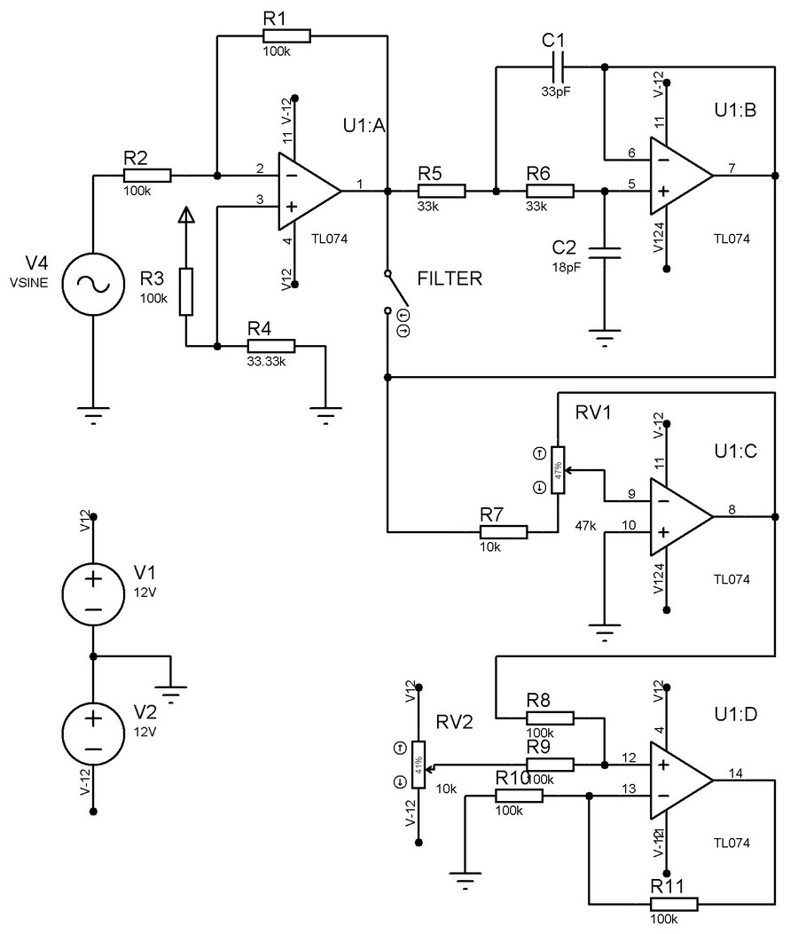
Here we have connected all four modeled parts: offset adjust, low pass filter, amplitude control, ofset control. TL074 chip comes with four operational amplifiers built in so we will get away with single chip and this functionality. If you are interested in simulating here is LTspiece simulation file. In simulator TL074 were replaced with similar LT1359 op amp, so actual results shouldn’t differ much.
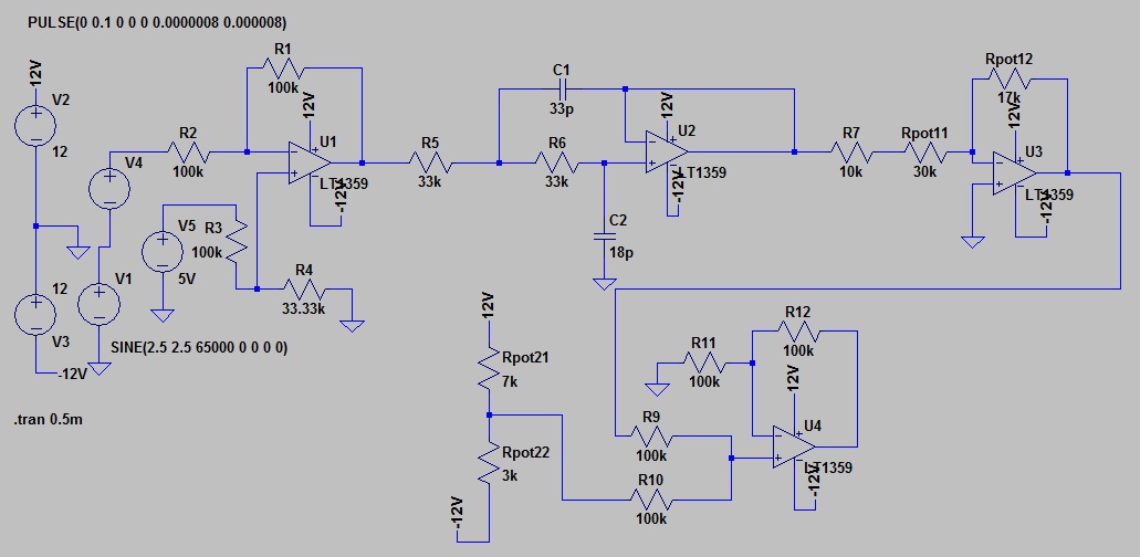
And corresponding signals on various nodes:
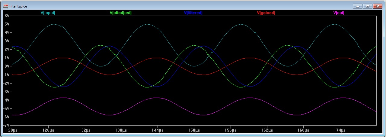
As you can see on first stage we have a sine signal with small distortion added and its offset is 2.5V. After offset adjust signal still is distorted but it crosses 0V now. After filtering we see no more distortion – only smooth sine. Then next stage adjusts signal voltage gain and on output we get signal with selected offset somewhere at -5V. Results looks promising so next step will be to put everything in to working project. Comments and suggestions are welcome.