Pulse-width modulation (PWM) generators are integrated in nearly every switching power device. This article shows two methods for implementing a stand-alone analog PWM waveform generator. These designs can also be modified to make a dual-device PWM generator.
There are two ways to implement a single-device PWM waveform generator. One method uses an ICM7555 timer, while the other uses a MAX998 low-power comparator. We will look at each.
Method 1: Use a Low-Power Timer as a PWM Generator
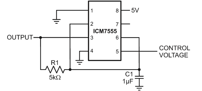
In this method an ICM7555 timer is configured as in Figure 1.
 |
|
| Figure 1. | A PWM generator and timer for a single device. |
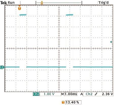
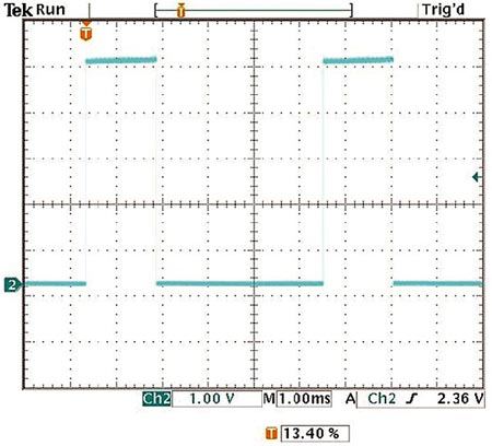
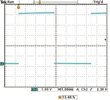
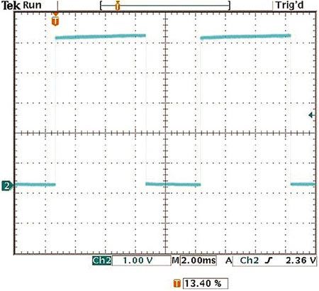
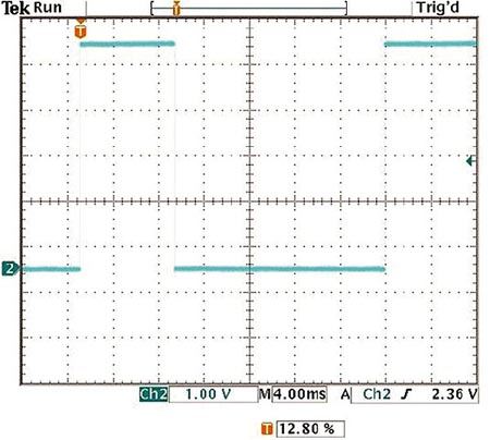
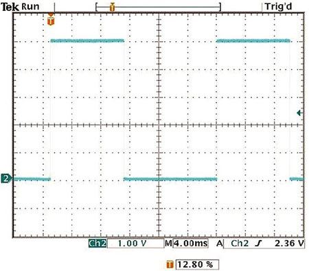
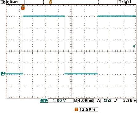
In Figure 1 the pulse width of the output at Pin 3 is modulated by the control voltage (VCONTROL) applied at Pin 5. Lab tests were done on the design with the power supply set at 5 V. Figures 2 through 5 show the PWM output at three different control voltages, 1 V, 2 V, and 4 V. C1 is charged to VCONTROL by the supply voltage (VSUPPLY) and discharged from VCONTROL/2 to ground. When no external control voltage is applied, VCONTROL is at 2/3 of VSUPPLY.
 |
|
| Figure 2. | PWM output with control voltage = 1 V |
 |
|
| Figure 3. | PWM output with control voltage = 2 V |
 |
|
| Figure 4. | PWM output with no control voltage |
 |
|
| Figure 5. | PWM output with control voltage = 4 V |
The data illustrate how the control voltage applied at Pin 5 changes the threshold voltage of the two internal comparators. Without the applied control voltage (Figure 4), the device sets the charging and discharging of C1 at 1/3 and 2/3 of the supply voltage. This is equidistant from the supply voltage and ground, thus effecting a 50% duty cycle. The different control voltages change the charging time for C1 to reach VCONTROL and the discharging time for C1 to discharge to VCONTROL/2. This process alters the pulse width of the output waveform.
The charging time is expressed as:
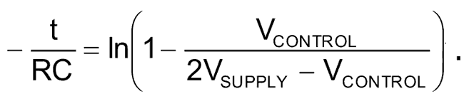
Where R = R1 and C =C1.
The discharging time is expressed as:
Method 2: a PWM Generator with Comparator
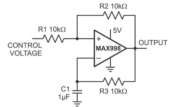
In this method a MAX998 comparator is configured as in Figure 6.
 |
|
| Figure 6. | A PWM generator and comparator |
The pulse width of the output is modulated by the control voltage applied at R1. Lab tests were done with the power supply set at 5 V. Figures 7 through 9 show the PWM output of three different control voltages, 1 V, 2 V, and 3 V.
 |
|
| Figure 7. | PWM output with control voltage = 1 V |
 |
|
| Figure 8. | PWM output with control voltage = 2 V |
 |
|
| Figure 9. | PWM output with control voltage = 3 V |
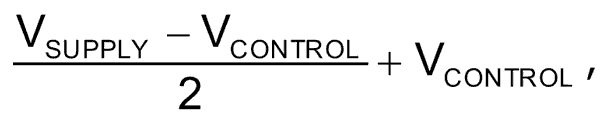
The control voltage applied to the MAX998 sets the threshold voltages at which charging and discharging occur. The upper threshold voltage is
and the lower threshold voltage is VCONTROL/2.
The charging time is expressed as:
The discharging time is expressed as:
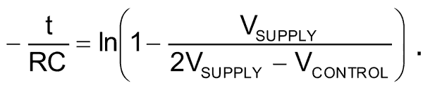
Where R = R1 and C =C1.
Modifications for a Dual-Device PWM Generator
It is important to note that the control voltage also changes the frequency in both circuit methods. Thus, adding an additional comparator to the circuits of Method 1 and Method 2 transforms each into a fixed-frequency, dual-device PWM generator.
For Method 1, feed the saw-tooth signal at Pin 6 into an input of the second comparator. A voltage applied at the second comparator’s input sets the duty cycle of the fixed-frequency output. Similarly for Method 2, feed the saw-tooth signal at the MAX998’s negative input into the input of the second comparator. A voltage applied at the second comparator’s input sets the duty cycle of the fixed-frequency output.