Many communications and sensor applications require a bandpass filter with wide bandwidth. This filter typically requires precision resistors and capacitors to obtain an accurate filter position and response.
Switched-capacitor filters eliminate the need for precision components, but require a clock from a microcontroller to set the center frequency. With the limited number of outputs and timers on popular low-cost microcontrollers, there may not be a clock timer or digital output to dedicate to the filter’s clock function.
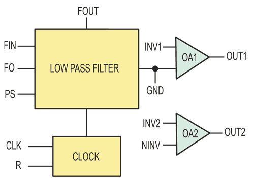
The solution is to use a filter with a built-in clock oscillator such as the MSELP fifth-order elliptic low-pass filter from Mixed Signal Integration (Figure 1). Similar ICs such as the higher-current (5 mA) LMF60 are available from Texas Instruments, under the legacy National Semiconductor designation.
 |
|
| Figure 1. | The MSELP Block Diagram. |
With the selectable 50:1/100:1 clock-to-corner-ratio pin and two uncommitted op amps, the clock-oscillator IC provides both an anti-aliasing filter and a reconstruction filter. Further, the clock output of the MSELP can drive another switched-capacitor high-pass filter. With a clock-to-corner frequency ratio of 1000:1, the MSHN6 sixth-pole high-pass/notch filter puts a decade between the corners of the bandpass filters.
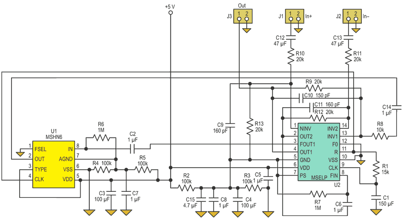
The circuit of Figure 2 is a 330-Hz to 3.3-kHz bandpass filter for Family Radio Service (FRS) radio or telephony. FRS radios are low-power, low-cost point-to-point units providing direct voice links between users without the need for an intermediate basestation or control node. They are especially useful in remote areas that lack cell-signal coverage or cell towers.
 |
|
| Figure 2. | This circuit provides a wideband bandpass filter optimized for FRS applications, with a 10:1 ratio in its corner frequencies. |
The corner of the reconstruction filter and the anti-aliasing filter is set for approximately 50 kHz. The design uses both anti-aliasing filters and reconstruction filters. The MSELP’s op-amp input provides both positive and negative inputs to the filter input. The MSHN6 and MSELP work down to 2.7 V dc. The circuit draws less than 1 mA. R1 and C1 set the oscillator frequency. With a 5-V supply, the frequency is:
For a 312-kHz clock, R1 is 15 kΩ and C1 is 150 pF (3.12-kHz low-pass and 312-Hz high-pass corners).
|
|||||||||||||
| Figure 3. | The network analyzer output shows the filter’s 3-dB points, roll-off, and attenuation through the anti-aliasing filter, two switched-capacitor filters, and the reconstruction filter (a); the amplitude (green trace) and group delay response (yellow trace) (b); and the reconstructed time-domain filter output at 1 kHz (c). |
||||||||||||
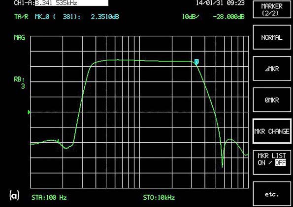
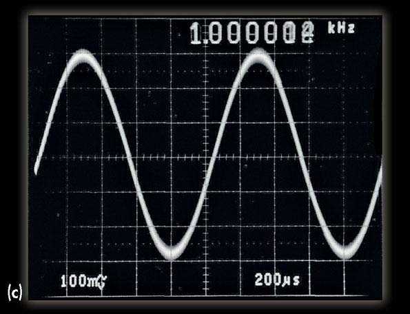
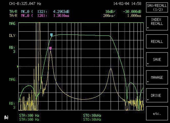
Figure 3a is a screen capture of the network analyzer showing the complete response through the anti-aliasing filter, two switched-capacitor filters, and the reconstruction filter. Figure 3b shows the amplitude and group delay response. Note that due to its group delay response, this filter would not be suitable for telecom use, but it is a fit for radio and telephony applications. Figure 3c is the filter output at 1 kHz in the time domain. Clock feed-through is minimal, as seen at the reconstruction filter output.