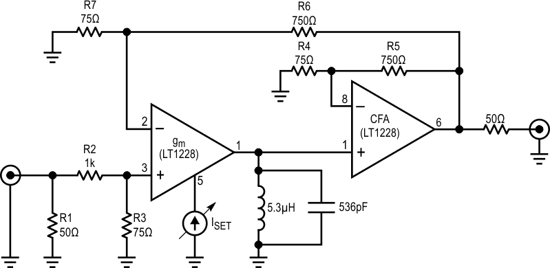
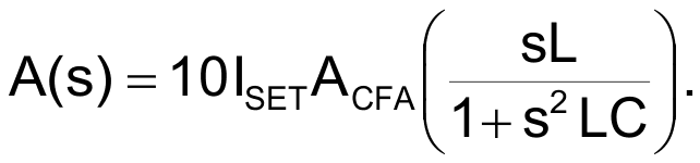
The bandpass filter circuit shown in Figure 1 features an electronically controlled Q. Q for a bandpass filter is defined as the ratio of the 3 dB pass bandwidth to the stop bandwidth at some specified attenuation. The center frequency of the bandpass filter in this example is 3 MHz, but this can be adjusted with appropriate LC tank components. The upper limit of the usable frequency range is about 10 MHz. The width of the passband is adjusted by the current into Pin 5 (set current or ISET) of the transconductance amplifier segment of IC1, an LT1228. Figure 2 is a network analyzer plot of frequency response versus set current. This plot shows the variation in Q while the center frequency and the passband gain remain relatively constant.
 |
|
| Figure 1. | LT1228 bandpass filter circuit diagram. |
The circuit’s operation is best understood by analyzing the closed-loop transfer function. This can be written in the form of the classic negative feedback equation:

 |
|
| Figure 2. | Network analyzer plot of frequency response vs “Set” current. |
The forward gain is the product of the transconductance stage gain (gm) and the gain of the CFA (ACFA). For this circuit, gm is ten times the product of ISET and the impedance of the tank circuit as a function of frequency. This gives the complete expression for the forward gain as a function of frequency:
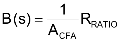
The reverse gain is simply:
and
Setting
and substituting these expressions into the first equation gives:
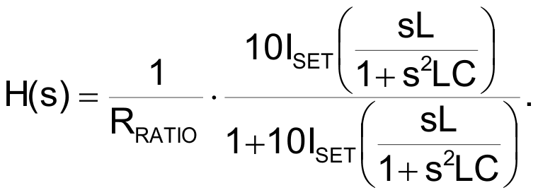
The last equation can be rewritten as:
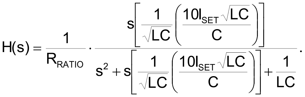
The transfer function of a second order bandpass filter can be expressed in the form:
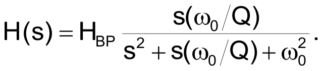
Comparing the last two equations note that
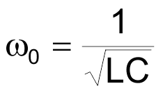
and
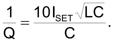
And therefore
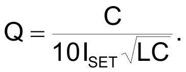
It can be seen from the last equation that the Q is inversely proportional to the set current. Many variations of the circuit are possible. The center frequency of the filter can be tuned over a small range by the addition of a varactor diode. To increase the maximum realizable Q, add a series LC network tuned to the same frequency as the LC tank on Pin 1 of IC1. To lower the minimum obtainable Q, add a resistor in parallel with the tank circuit. To create a variable Q notch filter, connect the inductor and capacitor at Pin 1 in series rather than in parallel.
A variable Q bandpass filter can be used to make a variable bandwidth IF or RF stage. Another application for this circuit is as a variable-loop filter in a phase locked loop phase demodulator. The variable Q bandpass filter is set for a wide bandwidth while the loop acquires the signal and is then adjusted to a narrow bandwidth for best noise performance after lock is achieved.