I stood in stunned silence at the smoke billowing up from the hardware on the workbench. Just moments before, it had been operating as expected, before self-destructing with a sound that can only be compared with a gunshot. The failure of the hardware under test had an unexpected consequence: the computer that had been using a USB-to-UART converter to communicate with the hardware experienced a USB fault that was not recoverable. The computer was now damaged and worthless.
A simple isolation circuit that costs only a few dollars could have been used to protect the USB port on the computer. Embedded system developers get used to plugging strange hardware and components into their computers on a daily basis and rarely consider the consequences of what their actions might bring.
This Design Idea documents a low-cost, isolated USB-to-UART converter using the Sparkfun USB-to-UART breakout board (BOB).
There are a number of times when an isolated USB-to-UART converter can come in handy. For example, during development of battery powered devices, there is a tendency to leave the USB-to-UART converter attached to the device, which, without isolation, will connect it through the host’s ground to an Earth ground. The device may work perfectly, but when detached from the computer, it doesn’t work at all. The isolated converter will keep the device and host grounds separate, allowing any grounding issues to be found early on rather than later.
The most important use of an isolated USB-to-UART converter is of course in fault conditions. Consider the consequences of connecting an untested electronic board to an expensive laptop such as a MacBook Pro. The USB specification and hardware layer does have protection circuits, but they may not be rated for devices operating at hundreds of volts DC. When a device fails on the USB bus and has the potential to put more than 5 V, or significant current, onto the bus, it is a wise decision to spend $20 and isolate the two devices.
Selection of an isolator
The isolator selection requires careful consideration. UARTs have traditionally been considered low speed devices but modern microcontrollers and interfaces can support baud rates in excess of 1 Mbps. Many isolators, especially opto-isolators, have maximum baud rates under 100 kbps. The Si8421BB-D-IS from Silicon Labs turns out to be a really good match to this application, but is no longer recommended for new design. An alternate is the ADUM3211ARZ, but this part was not tested, so use at your own risk.
The SI8421BB supports 2.5 kV of isolation for 1 minute. The BB designation shows that the isolator is capable of baud rates up to 150 Mbps. The low volume cost for the SI8421BB-D-IS is only $1.46, but if that is too expensive then the SI8421AB-D-IS is only $1.05 (with a maximum baud rate of 1 Mbps). Another advantage of the SI8421BB-D-IS is that it has two isolators in the 8-pin SOIC package, which is perfect for a Tx/Rx signal pair. The isolators are unidirectional, but laid out such that they are pin-compatible with the Sparkfun USB-to-UART BOB if proper care is taken.
Building one
There are a small number of parts that need to be ordered:
|
Quantity
|
Component
|
Source
|
Part Number
|
Price
|
|
1
|
USB-to-UART
|
Sparkfun
|
BOB-12731
|
$14.95
|
|
1
|
SOIC Breakout
|
Sparkfun
|
BOB-00494
|
$2.95
|
|
1
|
0.100” Headers
|
Sparkfun
|
PRT-00116
|
$1.50
|
|
1
|
SI8421BB-D-IS
Isolator |
Digikey
|
336-1756-5-ND
|
$1.46
|
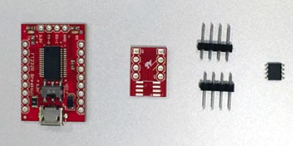
The total cost for these components is around $20 plus shipping. Most developers have at least one project running at a time so purchasing enough material to build two or three units helps to offset the shipping cost. The complete set of components should look similar to that of Figure 1.
 |
|
| Figure 1. | Isolated USB-to-UART components. |
Assemble the isolator
 |
|
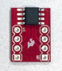
| Figure 2. | SOIC-8 BOB preparation. |
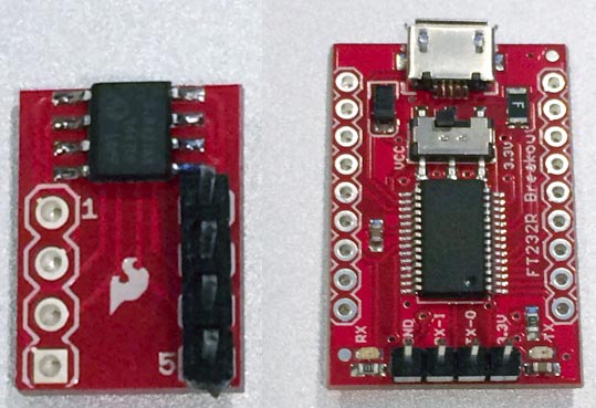
Start by soldering the isolator to the SOIC BOB (Figure 2). Then, add headers to both boards as shown in Figure 3.
 |
|
| Figure 3. | Header placement. |
The USB-to-UART BOB requires a four pin header where Gnd, Tx, Rx, & VCC are located.
 |
|
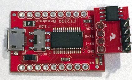
| Figure 4. | Assembled isolated USB-to-UART converter. |
The isolation board can now be soldered directly to the USB-to-UART BOB (Figure 4). Pin 1 of the SI8421BB-D-IS is power and should be aligned with the 3.3 V that is supplied by the FT232R IC on the converter board. The assembly of the isolated USB-to-UART converter is now complete!
Testing the converter
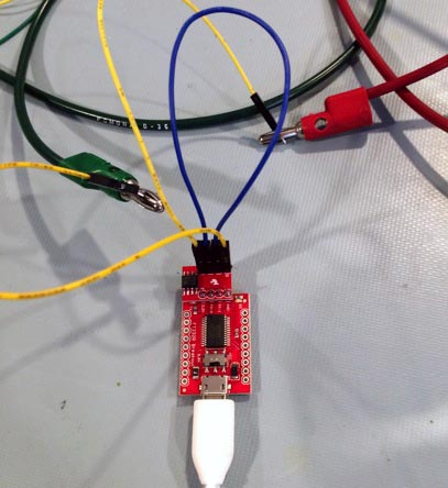
The USB-to-UART board is powered by USB 5 V through the USB cable that is connected to the host. The onboard FT232R outputs 3.3 V which powers side 1 of the isolator. Side 2 needs to be powered by the DUT’s hardware, and can be either 3.3 or 5 volts. The easiest way to test the isolated converter is to supply power and ground to side 2 of the SI8421BB-D-IS and then create a loopback by connecting Tx to Rx (Figure 5). The nice thing about the isolation board setup is that the unlabeled pins on the SOIC-8 BOB directly correlate to the USB-to-UART silkscreen, so that Vcc, Tx, Rx, and GND are all aligned.
 |
|
| Figure 5. | Testing the converter. |
Finally it is time to test the board. Fire up your favorite terminal application and open the VCP (virtual COM port, as created by the FTDI device driver). Just to push the limits, I set my terminal to the maximum of 921.6 kbps. Typing into the terminal should send data out the isolator, which loops it back in, and characters should appear on the terminal (Figure 6). If problems arise, the USB-to-UART board does have Tx and Rx LEDs onboard. Typing in the terminal should illuminate both. If one of them is not lighting up, then you know which side of the isolator to start looking for problems on.
 |
|
| Figure 6. | Loopback test of the isolated USB-to-UART converter. |
Final thoughts
At a minimum, building this simple isolation board helps to provide protection that wasn’t there in the first place. As a further ruggedizing step, you could add ESD protection to the UART side.