Offline power supplies that drive loads of 200 W and more require inrush-current limiters. Unrestricted inrush currents can reach hundreds of amperes, which may damage the line rectifier, open the fuse and input-filter inductors, and damage the PFC (power-factor-correction) filter capacitors. A simple method of limiting the inrush current uses an NTC (negative-thermal-coefficient) thermistor that connects in series with the supply line. When cold, the thermistor presents a high resistance, but its resistance decreases significantly as its temperature increases, limiting the inrush current by virtue of its thermal inertia and inability to quickly decrease its resistance.
However, an NTC thermistor also presents some resistance to the power supply’s normal operating current. To keep the thermistor’s normal resistance low, it should operate at a sustained and relatively high temperature, but this scenario may impair the power supply’s temperature profile and raise the temperature in an enclosure in which power dissipation is already substantial.
This Design Idea offers an alternative circuit that effectively limits inrush current and does not add an extra source of heat to the power-supply package. Without increasing power losses during normal operation, a switchable series resistor in the power supply’s dc section can efficiently limit inrush current until the PFC-rail electrolytic capacitors acquire a full charge. Then, an electromechanical or optically isolated semiconductor relay short-circuits the resistor.
However, determining whether the PFC capacitors are fully charged presents a problem. Universal power-supply designs operate over a range of ac-input voltages, and determining the voltage that indicates a full charge can thus prove elusive. In addition, the inrush-current limiter should delay operation of any internal auxiliary power supplies and other power-consuming circuits to allow the PFC-rail capacitors to charge to their full predetermined extent.
The easiest method of solving these problems uses a circuit that measures the inrush current itself and not the voltage across the PFC capacitors. It determines the end of the inrush process by monitoring extinction of the inrush current’s amplitude. Upon reaching a preset threshold, the circuit commands the start-up of auxiliary power supplies and other circuits. Monitoring the inrush current allows effective control of the power supply’s starting point and renders the start-up threshold independent of the input-line voltage.
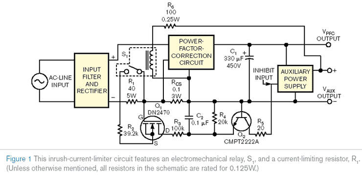
Figure 1 shows a practical version of a PFC circuit, which employs a switched-resistor inrush-current limiter. The inrush-current-sensing subcircuit comprises a wirewound resistor, R1, and a parallel depletion-mode MOSFET, Q1, which connects to resistor R2 as a current source that drives resistors R3 and R4. Over a wide range of the voltage drop across R1, from a few hundred volts to a few volts, this circuit generates a small constant current that suppresses operation of the auxiliary power supply and prevents interference with the inrush-current-limiting process.
When the inrush current decreases sufficiently, the voltage drop across R1 becomes insufficient to keep Q1 in operation as a current source. Q1’s current extinguishes, allowing the auxiliary power supply to turn on and start the power supply, by activating relay S1, whose contacts short-circuit R1. R2’s value determines the current necessary to hold the auxiliary power supply in a disabled mode, allowing PFC-rail capacitor C1 to charge fully.
A 12 V electromechanical relay, such as Omron’s G2RL-1, provides low-resistance contacts to bypass R1. As an alternative, an optically isolated solid-state relay, such as the Carlo Gavazzi RP1A48D5, with a MOSFET or an SCR (silicon-controlled-rectifier) output device can replace S1, provided that the voltage drop across the output device introduces no substantial power loss.
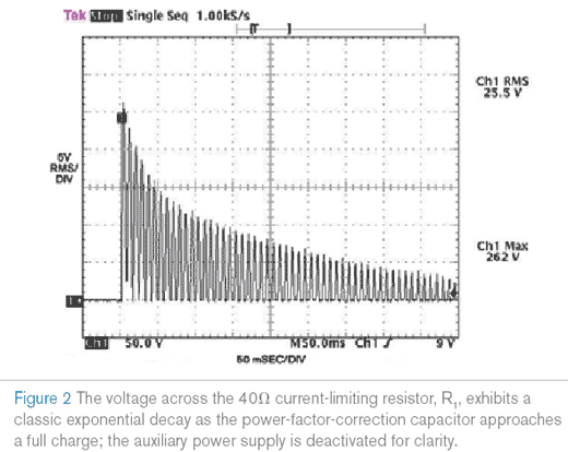
Figure 2 depicts the charging process’s waveform as the voltage drop across R1. The exponential envelope and its subcycles represent components of the inrush process; R3 and C2 filter out the subcycles and produce a decreasing exponential voltage waveform across R4, holding Q2 on for the duration of the inrush process. Q2 suppresses the auxiliary power supply’s operation by pulling its disable input low. At a few volts across R1, Q1 stops generating constant current and shuts down Q2 to enable the auxiliary power supply. Thus, the entire power supply waits until the inrush current attains a safe value that R2 sets. The power supply starts immediately after relay S1 trips and shorts out inrush resistor R1. The remainder of Figure 1 comprises a conventional PFC but may also represent a part of any other power-supply configuration.
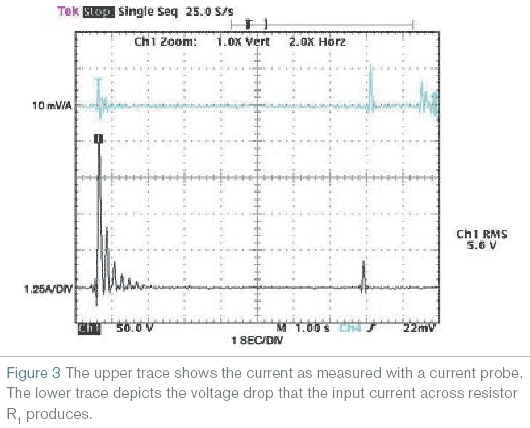
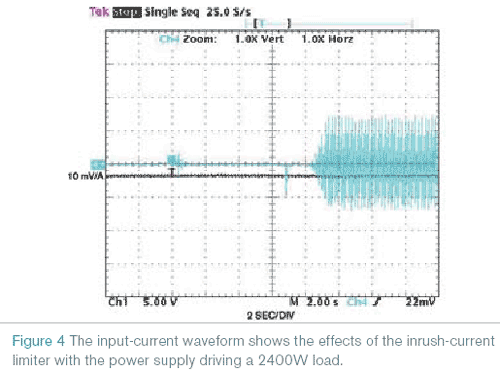
Trace 1 in Figure 3 depicts the start-up of a 2.4-kW power supply with the inrush-current limiter and a slow-start circuit, which allows the separation of the inrush and the start-up processes. The inrush-current value is 5 A, a relatively low value for a 2.4-kW power level. Trace 4 shows the input current measured with a current probe. Figure 4 depicts a 2400 W power-supply start-up. Its inrush current is intentionally approximately 5 A, which is far less than its operating current of approximately 14 A.
EDN