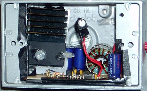
Current version, in a cast aluminum junction box.
This DC-DC converter is designed to accept a range of input voltages that are present in a car's electrical system, and provide a regulated 12 v output. Nominally, the battery voltage is about 13.8 v, but when the engine is being started, the voltage can often droop down to 6 or 7 v for a short time, and peaks can be present somewhat above the nominal voltage as well. Because the input voltage can be either above or below the desired output of 12 v, the converter needed to be a buck-boost configuration.
This project is now in the general electronics section, because I no longer use it in my MP3 Box, so now it's basically just a fun experiment that I did to explore the world of switching converters.
That is the design I am going with for my system, since the parts are cheap and more easily available. While based on a more antiquated controller IC, without the fancy features the newer-generation ones have, like charge-pump gate drive, it gives me a good starting point to tweak a more advanced design if need be. Not to mention, he claims it handles up to 8 amps output, and considering my MP3 box only drew less than 2 amps when I tested it last, I think that will be more than sufficient.
For those of you who are into this sort of thing and don't want to read the other page, this particular design is a SEPIC topology using a UC3843 controller chip. In addition to the two main inductors you normally see in a SEPIC design, there are two 12uH inductors, one each on the input and output. The two "main" inductors in this case are hand-wound on a common core, as coupling them is supposed to improve efficiency.
To wind the big black inductor you see in the pictures, which is the transformer-looking thing in the schematic, you need a $5.29 snap-on EMI suppressor from radio shack, part number 273-105, and you need some 18-20 gauge "magnet wire" (enamel-insulated copper wire). The magnet wire at radio shack is too small, you'll have to look elsewhere. Winding it is simple, you just need to wind two pieces of wire together, for 13 turns, around one half of the core. Then cut two strips of paper to place between the two halves of the core where they would touch. (Keeping the two halves of the core slightly separated with paper makes it not saturate as easily... ie - keeps bad things from happening) Then, eventually you should glue it all together so the core can't vibrate. Personally I chose not to glue it until I was sure it was performing properly.
Downloads
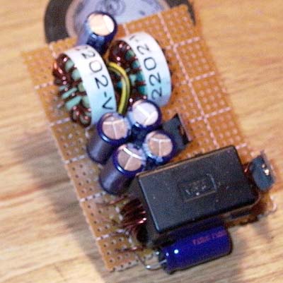
Here's a pic from the first prototype, an ugly thing on perfboard...
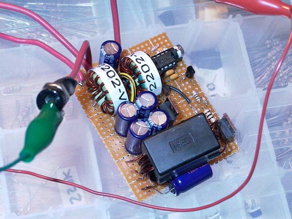
Here's a shot of it after I finished putting on all the control components...
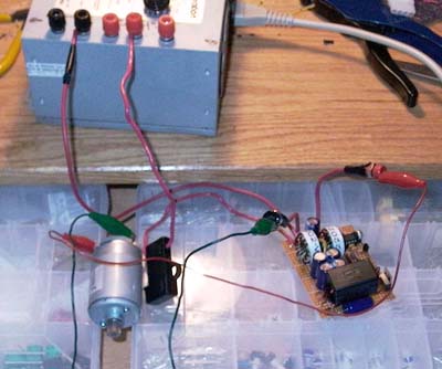
And finally a shot of my initial test setup:
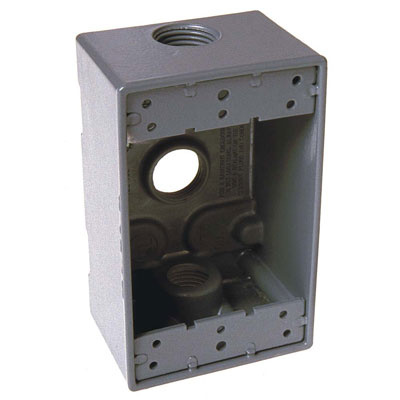
They're cast aluminum, so they're VERY rugged
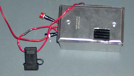
I tested this perfboarded prototype with some beefy power resistors, and it survived 85 watts output, however the output voltage steadily declined, I suspected it was caused by: A) power supply it was running from was rated at only 8 amps output, B) the transistor and diode were heating up quickly, and C) the load resistors may not have been happy about being heated to be too hot to touch in just 30 seconds...
Anyway, I was getting around 75% efficiency. I have since etched a proper PCB for it, re-using many of the components from the prototype. I haven't had a chance to run any serious tests, but it seems to be much better... for one thing, at first measurement I was getting 88% efficiency at 24 watts output, which is a lot better than 75%... And the transistor/diode are both mounted to a real heatsink this time... not to mention random parasitics of the crappy wiring job of the perfboard are much improved on the PCB.
First rev of the PCB. As always, after ma sking one and populating it, I discovered a few things I'd like to change, namely the addition of a pot on-board for output voltage tweaking... as it is I had to put it on a pigtail. I made the power to the chip go through a jumper so that I was able to remove the jumper, and wire the power to the chip to a switched 12 v line from my shutdown controller, allowing me to turn the DC-DC on and off.
Heat Sinking
One challenge has been heat sinking the transistor and diode. First off, I had to hack up a larger heatsink to fit on my board, which took some time. Secondly, you need to be very careful. You CANNOT allow the mounting tabs of the transistor and diode to be shorted together... In other words, you can't simply bolt them both to a single, metal heatsink. In this version, I bolted the transistor to the heatsink, as it is the major heat-generator, and placed a heat-conductive insulator (specifically for mounting transistors to heatsinks) behind the diode, and used a plastic zip-tie to hold the diode to the heatsink, so that the diode is not actually in electrical contact with the heatsink at all. Other options would be using separate heatsinks (probably requiring board re-design) or using all nylon mounting bolts and insulators. Whatever works for you...
Another design I found quite interesting can be found at http://mastero.tk His designs incorporate a full-blown power supply, including all the power rails needed. This would allow me to replace both the ITPS regulator AND the PW200 DC-DC. However, to keep things simple and to get this working sooner, I am going to stick to a single output supply for the time being. NOTE: his site seems to be pretty hit-or-miss. I had serious trouble accessing it for quite a while. If you find it's not available, feel free to email me at evandude AT gmail.com and I'll see if I can help... I have an archived copy just in case.
Modifications
The converter itself proved capable of functioning during engine cranking, however the controller chip has a 7.5 v threshold for input voltage, below which it just shuts down. To fix this, I modified the original circuit so that the controller receives power through two diodes, wired as a simple OR gate, one from the input voltage, one from the output voltage, so when the input voltage droops the output voltage keeps the controller powered. I also added a simple transistor circuit whereby the controller is powered through a PNP transistor, with the base driven by a simple NPN-transistor inverter. This input is then driven by an external "enable" signal, which I have wired to my shutdown controller; by doing things this way, the shutdown controller can turn the converter on and off with a low-level signal, rather than having to drive a relay to supply/cut power to the converter. Someday I should add these modifications to the schematic, but currently I have the built as a freeformed, electrical-tape-wrapped blob of circuitry that's wired to the main board, rather than making a whole new board incorporating them.