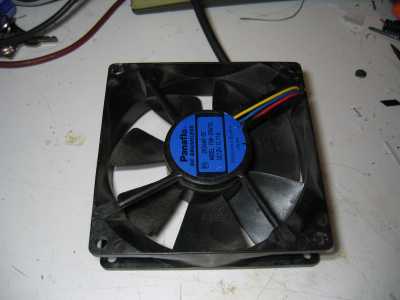
For a long time, I had the idea that a led-fan must be able to do something more than just give off a static light and move air. You've got moving parts, you've got a precise position read-out (the RPM wire of the fan), you've got a light-source that can be modulated... there must be something that can be done with that.
While I haven't found an use for a led-fan yet, the thinking process did give me another idea: It's possible to create a steady image of a fan using a stroboscope, which is nothing more than a device to create precisely-timed flashes of light. By adjusting the timing, one can make the image move clockwise and counterclockwise and in such a way adjust the angle it is in. Now, what would happen if we glue a paper needle to the fan? You could then in theory with some logic, put that needle in any angle you'd wish.
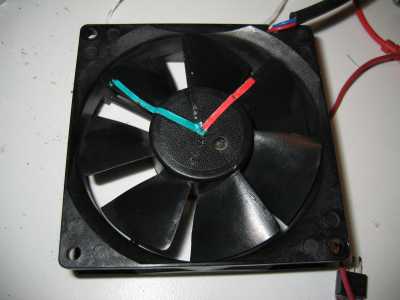
Thinking in that direction, I soon got the idea of creating a clock in such a way: make a red, a green and a blue 'hand' and by lighting up the three dies of an RGB-led, you can control exactly at what angle the image of every hand shows up. Apart from the hands, the fan itself doesn't need to be modified: the led, in conjunction with a microcontroller, does all the work.
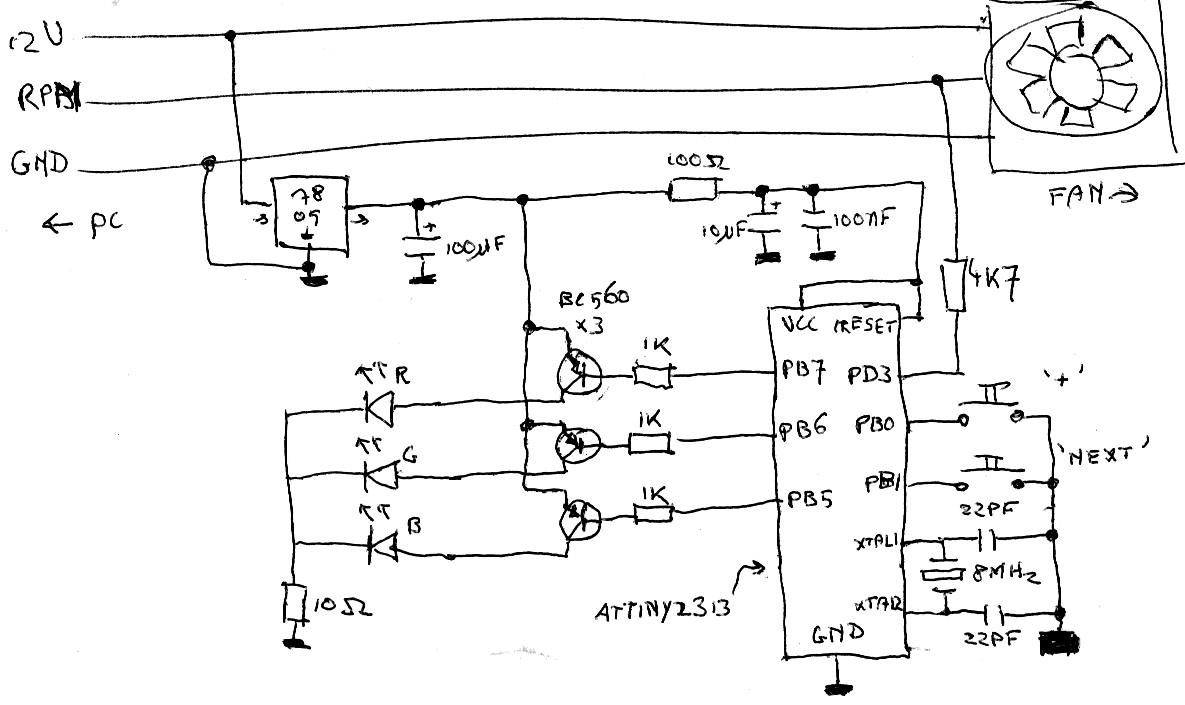
After some thought, I came up with the following scheme:
Top-left you can see the 7805 that distills 5 V from the 12 V that drives the fan. To the right is the power-supply for the uC, separated from the spike-inducing led-array by a 100 ohm resistor. Down right is the uC, with the two buttons used to set up the clock and the 8 MHz crystal. The rpm-output of the fan is connected to the uC via a resistor, to protect against accidental 12 V on the RPM-line. To the left, finally, are the leds, connected to the microcontroller using a couple of transistors: because the leds are only on 1/60th of the time, we can use the transistors and the 10 ohm resistor to pack an extra punch.
Just a note: as you can see, there's no battery backup or anything in the scheme. If you want the clock to keep it's time during powerdown of your PC, you can feed the uC from the standby-5 V on your ATX-connector: in that case, remove the 100 ohm resistor (I did't because I'm planning on putting the device in my server.)
Software
The software is written to enable the user to configure the clock at run-time using only two buttons: the '+'-button increases the current setting, the 'adv'-button saves the current setting and allows one to setup the next.
If the microcontroller is fresh from the programmer, the firmware doesn't yet know what the hardware looks like, so stuff like the type of fan and the angles the hands are on should be set up first. After that, the user can input the current time and after that's confirmed, the clock will start running.
The software mainly works by using three interrupts: the first one kicks in 500 times a second and is used for button debouncing and keeping time. The second one is dynamically adjusted to kick in 60 times per rotation of the fan and handles the showing of the hands by enabling and disabling the three colors of the RGB-led. The third one kicks in every time the fan generates an RPM-pulse. When that happens, the microcontroller will evaluate the speed at which the rotation-timer happens and adjust it when necessary.
The software for the clock is written in avr-gcc and released under the GPL v3, so if you want, you can modify it to display a clock on anything rotating quickly enough. If you come up with something interesting, please let me know!
Video of the led-fan-clock in action: