Ken Whiteleather
Electronic Design
Current-mode control loops (particularly the popular 4- to 20-mA controls) are used in many industrial applications because of their immunity to induced EMI from motors, contactors, relays, and other sources. Off-the-shelf process controllers often have 4- to 20-mA (sometimes 0- to 20-mA) output options for adjusting speed, pressure, temperature, or some other parameter in a closed-loop control system.
The receiving circuit needed for the 4- to 20-mA control signal isn’t extremely complex, and several components are available that are designed specifically for this purpose. However, the cost of these parts was a bit higher than I expected (more than $10) in small quantities.
While looking for a low-cost alternative, I discovered the INA134 from Texas Instruments. It’s a very versatile, unitygain audio differential amplifier with a wide supply range. Using the dual version (INA2134) and just a few precision resistors, I came up with a 4- to 20-mA receiver circuit that costs less than $2.60.
The circuit in Figure 1 was simulated with MultiSim 8 (Electronics Workbench) using the INA134. (Translating the pinouts for the INA2134 is easily accomplished.) Circuit stimulus is provided by an ac current source centered at 12 mA with an 8-mA peak signal (resulting in a 4- to 20-mA swing) at 10 Hz. Any reasonable frequency can be used, but 4- to 20-mA controls are typically slow-varying signals.
 |
||
| Figure 1. | Designers can build a receiver circuit for a 4- to 20-mA control signal at a lower cost than commercial components available specifically for that purpose. |
|
One section of the INA2134 provides an offset for the output. The 1% resistors shown in conjunction with the laser-trimmed precision resistors within the INA2134 provide a fairly precise +2-V dc offset. The circuit runs off a 24-V dc single voltage supply, so this offset is needed to ensure the output doesn’t get too close to the ground rail. (The specification for the part limits the output to V+ – 2 V and V- + 2 V.)
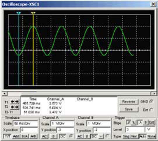
The 150-, 1% tolerance resistor across the input pins gives an output of 0.6 V at 4 mA input to 3 V at 20 mA input plus the 2-V offset for an output range of 2.6 V to 5 V (Fig. 2). This is the input to an analog-to-digital converter (ADC) in my application. The ADC output is interpreted by a small microcontroller that controls the process.
 |
||
| Figure 2. | The output of the receiver circuit is 2.6 V to 5 V, including the 2-V offset. |
|
Note that a 0- to 20-mA input would result in a 2.0-V to 5.0-V output range. For other applications, designers can adjust the output range and offset by simple changes in resistor values. The single supply voltage can be up to 36 V dc. If dual supplies are used (up to ±18 V dc), the offset isn’t necessary, and the INA134 single amp can be used with one input resistor, reducing the cost to less than $1.60.