PIC 18F4550 and 18F2550 are powerful microcontrollers including a full-speed USB V2.0 compliant interface. With these MCU it's very easy for the hobbyist to design USB devices with very few components. In these pages, I'm describing how to use the CDC firmware from Microchip. It permits to emulate a serial port with a PC running Windows or Linux. It's also very easy to build HID devices.
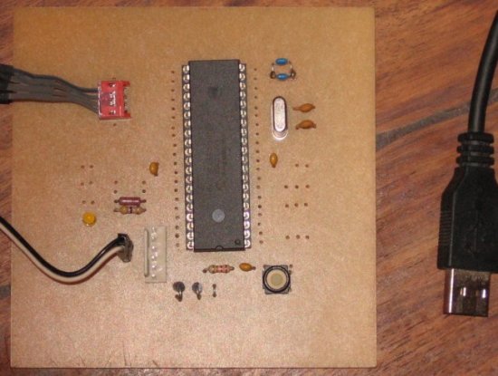
Picture of the experimentation board
The following schematic is very simple, only few components are needed. It's a self powered USB device. Please note I'm using the Olimex tiny-ICSD programmer, if you want to use another PIC ICSP programmer, you should remove D1 and D2 and change the connector.
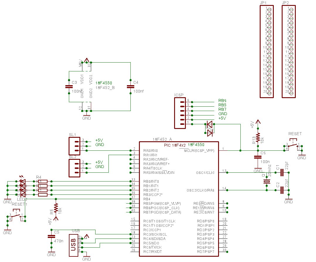
click to get an high resolution picture
This device is compatible with the microchip USB bootloader.
Please note C5 is 470 nF (the datasheet recommend 220 nF but more is better) and should be low ESR (for example a multi-layer ceramic). Don't forget the 100 nF decoupling caps.
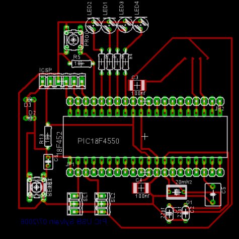
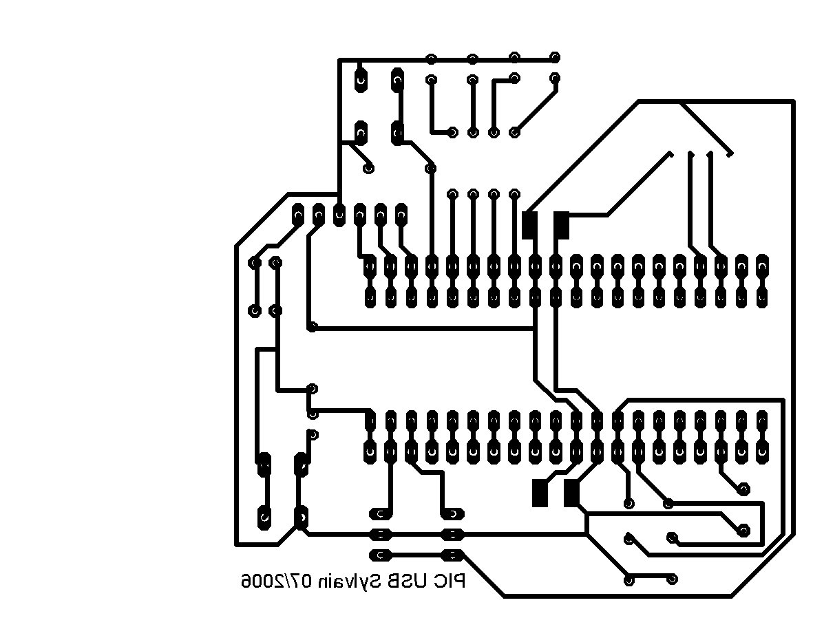
Here is a possible implementation.
You can look at the wire's colour of your USB cable: Black=GND, Red=+5 V, Green=Data+, White=Data-
4/1/2007 : IMPORTANT ERRATA - There's a little mistake in this PCB. R5 must be connected to +5 V, not to the ground. Do not connect R5 to GND, but to +5 V or it will not works at all.
The software
You can download MCHPFSUSB_Setup on the Microchip website. It's a windows .exe :(. The firmware we will use is written in C (for the C18 Microchip compiler). This code is (royaltyes) free, but it's not a free software, so it's not possible to redistribute modified source code.
In this archive, you will find:
- The USB bootloader and its source code in C18
- A windows utility for the bootloader
- The CDC firmware source code (serial emulation) in C18. It can be used with the USB bootloader without modification
- Another firmware for the HID device
- A windows driver for CDC (under linux CDC-ACM is natively supported)
Some tips for your prototypes:
The source code is in the fw/cdc/MCHPUSB.mcw directory
You should comment the following lines in usbcfg.h for a self powered usb device:
#define USE_SELF_POWER_SENSE_IO
#define USE_USB_BUS_SENSE_IO
On my schematic, LED's are connected on port B. So you should modify io_cfg.h
#define mLED_1 LATBbits.LATB0
#define mLED_2 LATBbits.LATB1
#define mLED_3 LATBbits.LATB2
#define mLED_4 LATBbits.LATB3
You can put your own code on user.c. For example, look at Exercise_Example() in user.c.
Useful functions are getsUSBUSART() (get data) and putrsUSBUSART() (put data other the serial port)
Don't forget to check mUSBUSARTIsTxTrfReady() before to send data.
They are some examples in the exercise directory. For example, the following program (to put in user.c) toggle the LED number 4 when you press the key "1" in the terminal
void Exercise_03(void){
if(getsUSBUSART(input_buffer,1)) {
 if(input_buffer[0] == '1') mLED_4_Toggle();
}
Under windows, you must install the provided driver and you can use the hyperterminal utility (19200bd with a 20 MHz crystal). Under linux, check the cdc-acm module, a new device /dev/ttyACM0 should appear.
If you don't want to use the bootloader, you must remove the vector remapping section in main.c and change the linker script (look at important.readme.txt in the sources directory).