The article describes an RGB incident light sensor that uses colored LEDs as narrow-spectrum photosensitive elements.
In the process of prototyping the RGB sensor, LEDs from the available batches were tested. However, the best results are obtained with noname super bright 3 mm colored LEDs purchased from AliExpress (Figure 1).
 |
||
| Figure 1. | Spectrum response of the RGB sensor. | |
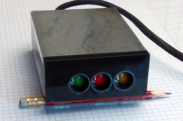
A red LED is used for the R-sensor, a yellow LED for the G-sensor, and yellow-green for the B-sensor. The RGB sensor is made in the form of a working design with dimensions of 80 × 100 × 30 mm and is used in practical laboratory activities (Figure 2).
 |
||
| Figure 2. | The appearance of the RGB sensor. | |
Photosensitive elements are equipped with 10-degree lenses enclosed in tubes that protect them from side illumination.
The schematic of the RGB sensor is shown in Figure 3. The channels R, G, B are identical, except for the value of the resistor R7, which is indicated conditionally and depends on the sensitivity of the LEDs used. Capacitor C1 limits the bandwidth of the amplifier and is optional. Resistor R3 is used to set zero at the output of the amplifier A2 when the photodetector V1 is darkened. Although using of the photodetector in photovoltaic mode provides a nonlinear conversion of the luminous flux into voltage, however, it provides high sensitivity and a low level of intrinsic noise.
 |
||
| Figure 3. | Schematic diagram of the RGB sensor. | |
When designing a sensor, the main attention should be paid to shielding the board, including lenses in the area where photodetectors are installed. Bad shielding will not allow you to get correct results!
Adjustment
The most important stage in the manufacture of an RGB sensor is the tuning process, for which we will need an RGB light source based on power color LEDs, the current through which is regulated over a wide range.
To obtain correct and stable results during the adjustment process, a laboratory stand is required, which in the simplest case is a piece of a furniture panel 50 cm long, at one end of which light sources will be placed and fixed, and photodetectors at the other. The RGB emitter LEDs must be mounted on heatsinks that prevent the crystal temperature from rising above 50 degrees, since the increase in temperature is accompanied by a change in brightness, and the results will “float”. The LEDs are equipped with 10-degree lenses (without lens elements), the outer end of which is sealed with a light-diffusing film, for example masking tape, which is transparent enough for light.Thus, we get a flat cosine light source that does not have a clearly defined directional pattern.
To measure illumination, we will need a photometer described at the end of the article, since inexpensive luxmeters have a dependence of readings on the wavelength of incident radiation and are unsuitable for our purposes.
The first stage of adjustment
Having placed the photometer at a distance of 30 cm from the LED block, as shown in Figure 4a, we turn on the LEDs one by one, each time placing the photometer on the geometric axis of the emitter (it is advisable to mark these axes before starting the adjustment). We remember the currents of the LEDs, at which the luminous flux Φ from them will be the same, i.e. ΦR = ΦG = ΦB.
The measurement should be brief in order to avoid changing the luminous flux due to the heating of the LED crystal.
The second stage of adjustment
In place of the photometer, we put the RGB sensor assembled and placed in the case, as shown in Figure 4b. Turn on the red emitter and change the resistance R7 to get the desired gain. We remember the output voltage of the red UR channel. Repeat these operations for the green and blue channels, adjusting the resistances R7 to obtain a voltage at the output of the channels equal to the voltage UR, i.e. UG = UB = UR.
 |
||
| Figure 4. | The position of the instruments on the stand when setting up the RGB sensor. | |
The bandwidth of the sensor amplifiers is regulated by capacitor C1. In our case, we limited the bandwidth to 20 Hz by using 22 nF capacitors.
The RGB sensor configured in this way is quite suitable for practical work.
Photometer for RGB sensor settings
And in conclusion, let's look at the photometer circuit that we used when setting up the RGB sensor. The basis of the device is the OPT101 photodetector IC, which is widely used in medical research. This photodetector can be bought from Aliexpress.
The OPT101 datasheet contains a graph of the spectral sensitivity (Figure 5), mirroring which we get a graph of the change in the gain of the corrective amplifier to obtain a uniform spectral response.
 |
||
| Figure 5. | Spectrum response of the integrated photodetector OPT101. | |
In our case, the gain values were:
- KR (640 nm) – 3.25,
- KG (525 nm) – 5.75,
- KB (445 nm) – 7.4.
Based on these values, we calculate the resistance of the resistors R1 - R3 according to the formulas:
These resistors are best made variable, as shown in the Figure 6 diagram, choosing their values so that the calculated value is reached in the middle position of the wiper.
 |
||
| Figure 6. | Schematic diagram of the photometer. | |
It is desirable to place the photometer in a housing that provides good shielding. In our case, we used clad fiberglass. Light enters the photodetector through a hole in the front wall with a diameter of 10 mm. The distance from the photodetector to the front wall is also 10 mm to reduce stray illumination.
Photometer setup
Since we need relative, not absolute, illuminance values, tuning comes down to a simple procedure, which consists in applying a highly stable voltage to input A2-1 and setting the required gains with resistors R1 - R3.
The proposed photometer is quite suitable for setting up an RGB sensor.The method of its application is simple. For example, when measuring the luminous flux from a blue LED, we set switch SW1 to a position where the gain of the corrective amplifier corresponds to blue, and so on.
Conclusion
The authors do not guarantee that any color LEDs will be suitable for the manufacture of an RGB sensor, therefore, when duplicating the device, it will be necessary to conduct a preliminary study of the light sensitivity of the available LEDs.