For my latest projects I used a lot of single cell lipo batteries. They are really nice. High power density, low self-discharge, no memory effect and they can deliver quite an amount of current.
But lipo battery handling is a bit more complicated as with other rechargeable batteries. You have to take care of under voltage and over charging as that may destroy the battery.
I used the Sparkfun LiPoly charger, based on MAX1555, for some time and it works really well. The only thing I missed was a way to control the current. After some research I decided to try another chip, the Microchip MCP73833.

Features of the MCP73833
Copied from the specs:
- High accuracy preset output voltage regulation
- Regulated output voltage options
- User-programmable charge current up to 1A
- Two open-drain Status outputs
- Preconditioning and end-of-charge ratio options
- Under-voltage lockout
- Power Good output
What I like is the ability to adjust the charging current and the status outputs, which should get really useful if integrated into a greater application.
The schematic
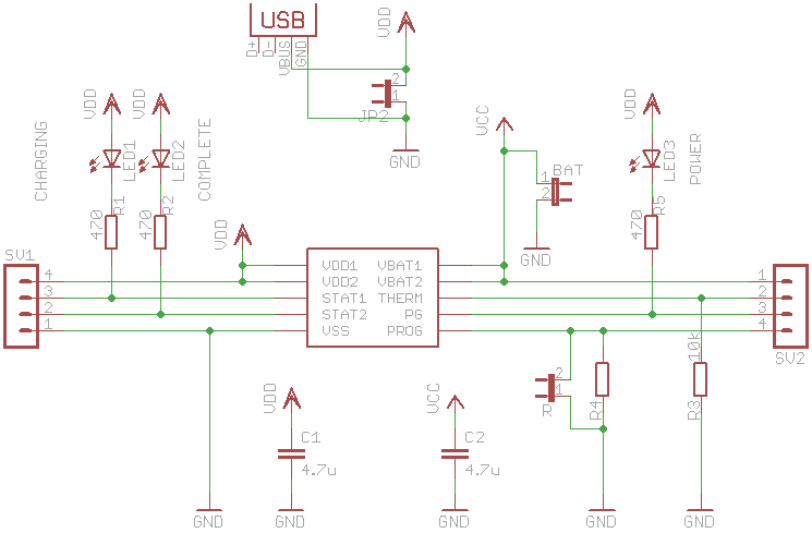
The schematic is mostly a copy of the reference design. It has three LEDs, one for power good, one for charging and one for charging complete. All pins of the chip itself are also available on two header rows. The idea was to enable easy integration on a breadboard. Actually I misplaced the rows, so they don’t fit (#fail).
The resistor R4 is used to control the charge current. I used a socket for that, so I am able to adapt the current for different batteries. The 10k resistor results in a charge current of 100 mA.
The result
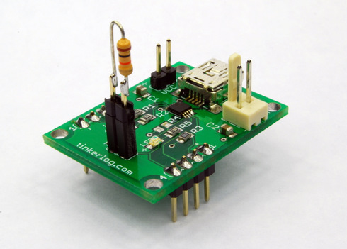
All components were 0805 SMD parts, despite the MCP73833, which is 10-MSOP. This was my first attempt to do something useful with SMD. I used my brand new hot air reflow station, which turns out to work as expected. Only I had to be very precise at dosing the solder paste. Applying too much had to be removed with solder wick later on.
Issues
The next version should include a jack for a wall adapter. The two header pins are not really useful to connect to a power supply. And of course the two rows of header pins should be aligned correctly to fit on a breadboard.
As a sidenote: as you see, the board has a mini-USB connector to be able to connect the charger to a notebook.
I stronly recommend to use some kind of USB hub to test any newly build USB hardware.
I didn’t. And now I have a burned first prototype of my charger and only one USB port left on my MacBook. Although the OS warned me with “something is sucking too much, port gets shut down”, it wasn’t fast enough. So, you have been warned.