Hackster.io
With a code size of 1 KB on an ATtiny13A MCU, this tiny module measures voltages up to 22 volts and current up to 5 amps.
There are a lot of so-called "USB doctor" modules which are used for monitoring currents flowing through a USB connection. They are used for cable or charger testing, quick charge detection and load current consumption measurements. They're cheap of course and someone may ask why should we build one? If you can do it better, then do it. So what's better about my design (Figure 1)?
 |
|
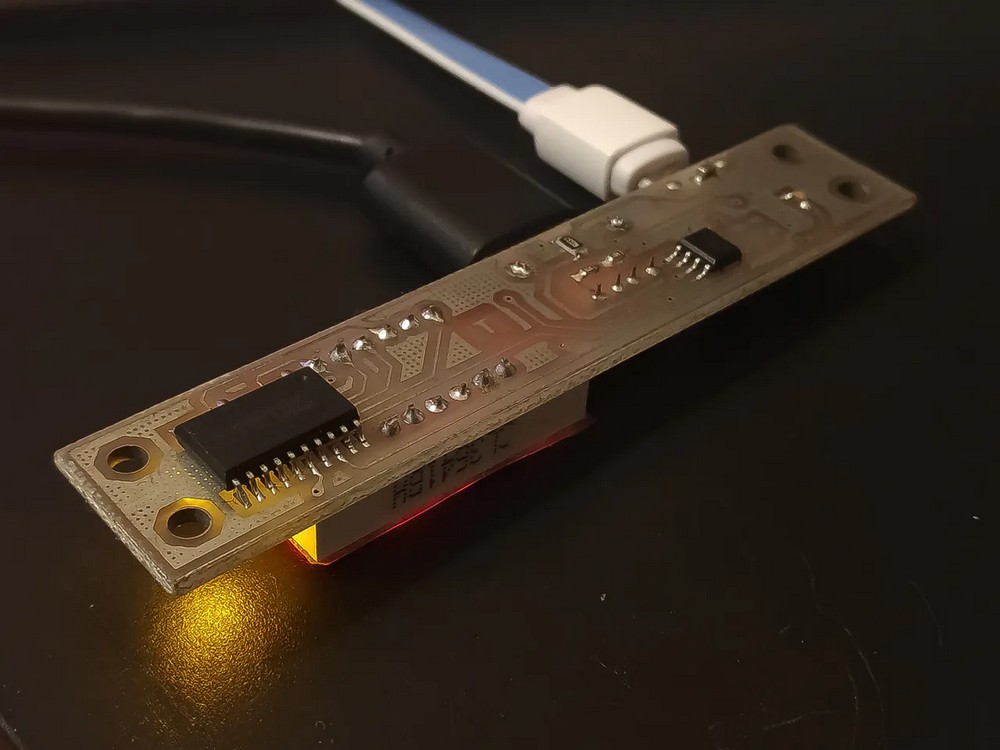
| Figure 1. | USB Voltage/Current Meter measures voltages up to 22 volts and current up to 5 amps. |
The USB Voltage/Current meter has the following features:
- Self-calibration: You don't need to know the exact resistor values used for voltage dividers. Just use a proper divider to map your desired voltage range into 0~1.1 V range (1.1 V is the internal V-ref of ATtiny13. The feature we needed it for). after that all you need to do is to connect the module to a precise 5v supply while holding the onboard button. the device starts up and shows "C" character on the display, calculates the divider values itself and saves them in the internal e2prom. So you just need to do it once.
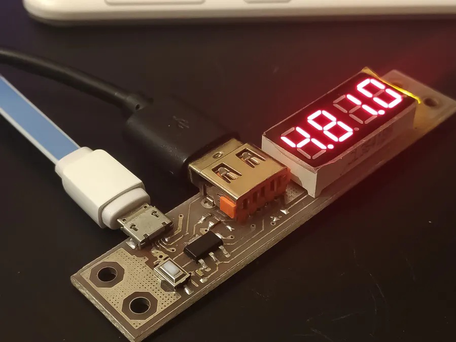
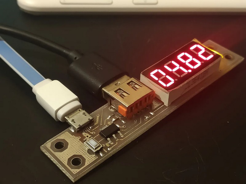
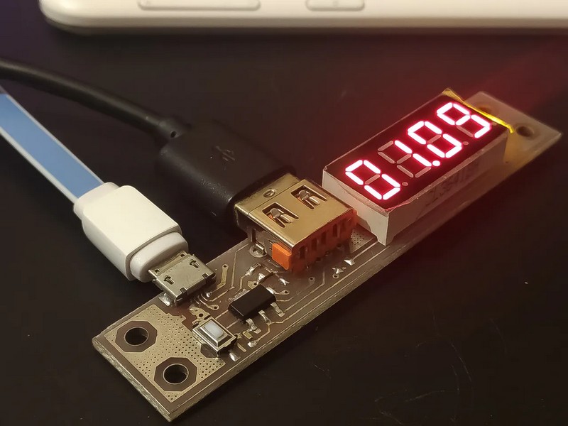
- Various display options: Using the button, you can switch between current display, voltage display and both. It is possible to save the preferred display on e2prom for startup (Figure 2).
- A 1 KB code challenge: Despite there are better options than using 2 chips (1 microcontroller + 1 display driver), I like the discrete designs. I had to implement a display library too. The display driver is universal and you can use it for any other microcontroller that supports an ANSI C compiler! read the libraries provided below.
|
|||
|
|||
|
|||
| Figure 2. | USB Voltage/Current Meter: Using the button, you can switch between current display (c), voltage display (b) and both (a). |
||
The author notices displaying both values side by side is not good for voltages above 9V as the second value can't be shown.
The design is based on an ATtiny13A microcontroller, a TM1637 LED driver and a 0.033 ohms current sense resistor (Figure 3). The 1.1 V ADC voltage reference on the ATtiny came quite handy for better precision. The whole Proteus project consisting of schematic and PCB (Figure 4) and can be downloaded.
 |
|
| Figure 3. | USB Voltage/Current Meter Schematic Diagram. |
 |
|
| Figure 4. | USB Voltage/Current Meter PCB View. |
I had to get rid of floating point calculations. Despite the voltage divider and the values shown on the display may seem to have radix points, they don't. The values are calculated as mA and mV and then a point is placed in the display at proper location. so there was no need to calculate float values.
Main code (C/C++) not deeply commented, but it's self explanatory. In TM1637 general driver library (C/C++) many of the characters which can be displayed on a 7 segment are removed from TM_DIGITS array due to constrained ATtiny13A flash. If you want to use it for another project, uncomment them. Other modifications are applied on the header file alone.
TM1637 general driver library, header file (C/C++) can be customized for other platforms or microcontrollers. read the comments.