Testing power supplies or discharging batteries usually requires a constant-current load. Sometimes, however, you must study the behavior when the load is a resistor. Using a highpower potentiometer is an expensive approach that might not be worth the cost. The circuit in Figure 1, which performs like a high-power resistor that connects between P1 and P2, provides an alternative approach.
 |
||
| Figure 1. | The resistance of the MOSFET, functioning as a variable resistor, changes. |
|
To understand how the circuit works, assume that the op amp is ideal and that the total resistance of R2 and R3 exceeds that of a high-power resistor (not shown). R2 and R3 form a divider that produces an output voltage, according to the following equation:
The operational amplifier maintains a voltage, such that R1’s voltage equals the reference voltage, that causes the current through R1 to be:
Substituting the first equation in the second equation yields:
If you neglect the current through R2 and R3, then R1’s current equals the input current, as the following equation describes:
This equation shows a linear relationship between the input current and the input voltage. Thus, the circuit between P1 and P2 acts as a resistor. The equation then becomes:
where
is a factor greater than 1, which multiplies R1. Making either R2 or R3 variable lets the circuit function as a variable resistor. The cost of a suitable transistor and R1, along with the rest of the components, is smaller than that of a variable potentiometer that can dissipate the same amount of power.
 |
||
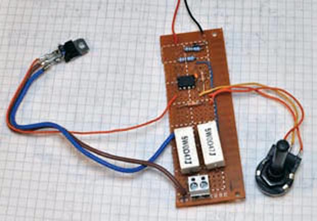
| Figure 2. | It is easy to assemble the circuit on a prototype board. | |
The circuit has some limitations, however. First, it can accept input voltages of only one polarity, which might limit its use in some applications. Second, the minimum resistor value is the value of R1 plus the transistor’s minimum on-resistance. Other factors such as op-amp offset, the values of R2 and R3, and input voltage influence the circuit’s linearity, but the circuit still achieves high performance with low-cost components. Depending on the op amp’s input range, the circuit requires an external dual power supply. Figure 2 shows a prototype of the tested and built circuit using a potentiometer for changing the equivalent resistance and no heat sink on the power transistor.