Overview
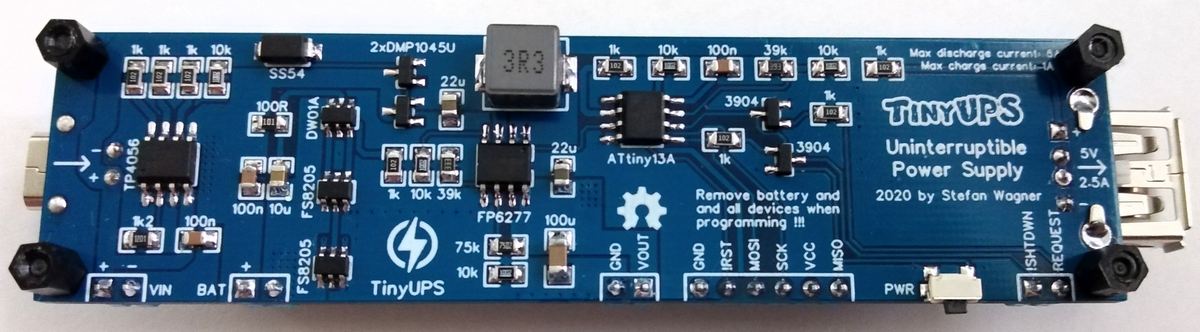
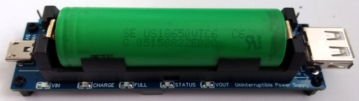
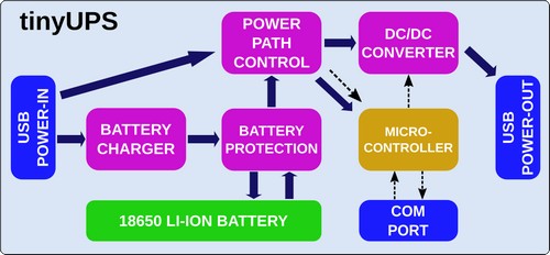
TinyUPS is a simple 5 V/2.5 A uninterruptible power supply with a li-ion battery as a buffer, a load sharing power path management system and an ATtiny13 for monitoring power supply and battery charge level as well as for communication with the connected device (Figure 1). TinyUPS Block diagram shown in Figure 2, you can see Project page on github.com [1].
 |
||
 |
||
| Figure 1. | TinyUPS is a simple 5 V/2.5 A uninterruptible power supply with a li-ion battery. | |
 |
||
| Figure 2. | TinyUPS Block diagram. | |
Working Principle
If external power is connected to the tinyUPS the input voltage or vcc of the ATtiny13 is delivered by this source, otherwise by the battery. The ATtiny13 monitors the input voltage and tells the connected device to shutdown by pulling the SHUTDOWN-line low when the input voltage falls below a certain threshold (SHUTDOWNLEVEL). This happens when the external power source is diconnected or disabled and the battery level falls below this threshold. After waiting a certain time (SHUTDOWNTIMER) to allow the connected device to safely shut down, the ATtiny13 deactivates the boost converter and turns off the power to the connected device. If the input voltage rises again above a certain threshold (POWERONLEVEL) it activates the boost converter and turns on the power to the connected device. This happens when the external power source is available again. When power is turned on a BOOTUPTIMER starts to count. If a shutdown is initiated before the boot up is completed, the left-over time is added to the SHUTDOWNTIMER in order to allow the connected device to completely boot up and shut down. A shutdown can also be initiated by pressing and holding the button or by setting the REQUEST-line to high (>0.7 V) for 2 seconds. After such shutdowns the power will not be turned on again automatically. The power to the connected device can be turned on manually by pressing the button or setting the REQUEST-line to high if the battery level is above a certain threshold (USERPOWERLEVEL) or the external power source is connected.
The SHUTDOWN pin of the tinyUPS is an open collector output. The connected device must have an internal or external pullup resistor on the SHUTDOWN line! This is necessary because of the different voltage levels.
The ATtiny13 spends most of the time in power-down sleep mode to save energy. The watch dog timer wakes it up every 8 seconds. It will also wake up if the button was pressed or the REQUEST-line was changed (pin change interrupt). After doing its stuff the ATtiny13 sleeps again. The current status of the tinyUPS is indicated by 5 LEDs (Table 1).
| Table 1. | Current status of the tinyUPS. | ||||||||||||||||
|
|||||||||||||||||
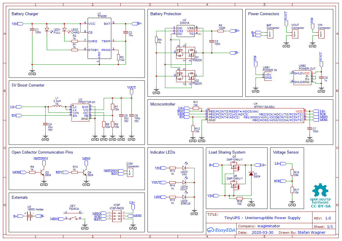
For battery charging the TP4056 is used. The TP4056 is a complete constant-current/constant-voltage linear charger for single cell lithium-ion batteries (Figure 3). The charge voltage is fixed at 4.2 V and the charge current (max 1000 mA) can be programmed externally with a single resistor (R3). The TP4056 automatically terminates the charge cycle when the charge current drops to 1/10th the programmed value after the final float voltage is reached. Other features include current monitor, under voltage lockout and automatic recharge.
 |
||
| Figure 3. | TinyUPS Schematic Daigram. | |
For the battery protection (overcharge, overdischarge, overcurrent and short circuit protection) the DW01A is used in combination with two FS8205 dual MOSFETs in parallel. The DW01A is constantly measuring the voltage across the battery and the current flowing in (when charging) or coming out (when discharging). If something goes wrong it takes the battery out of the circuit by closing the MOSFETs which act like a switch between the negative side of the battery (B-) and ground. The overcurrent protection works by comparing the voltage drop across the MOSFET with the internal 150 mV reference of the DW01A. As the RDS(on) of one FS8205 is around 2×25 mOhm, the DW01A would close the MOSFET at 150 mV/50 mOhm = 3 A if only one FS8205 were used. By using two FS8205 in parallel, the resistance is cut in half, so the DW01A shuts down at 150 mV/25 mOhm = 6 A and one FS8205 must only handle half of the current (3 A) which is well within its specs. In this way, up to 6 amps can flow from the battery into the boost converter with a maximum voltage drop of 150 mV.
To step up the voltage to 5 V the FP6277 low-cost synchronous boost converter is used. Instead of a diode that is used in conventional boost converters, it switches a second built-in MOSFET in sync with the first via the PWM signal. This significantly increases efficiency and thus higher output currents are possible.
The entire project is available in EasyEDA [3] and in download section.
Although it would be possible to supply the connected device via the battery and charge the battery at the same time, this is absolutely not a recommended way. In this case, most charging ICs such as the TP4056 are unable to determine whether the battery is fully charged because the current never drops below 1/10th of the programmed charging current value which would tell the device to terminate the charging cycle. The battery would be charged forever, which would destroy it in the long run. A load sharing system was therefore integrated, which separates the battery from the load when an external power is present. While the battery is being charged, the connected device is powered by the external power supply. For more details on the working principle of the load sharing power path management circuit refer to [2].
Performance
External power supply should be capable of delivering enough power to charge the battery and to power the connected device simultaneously. The maximum battery charging current is set to 1000 mA but you can set a lower limit by selecting a different value of R3. The output voltage of the external power supply must not exceed 5.2 V (Table 2)! Choose a good 18650 Li-Ion battery with a low internal resistance which is capable of delivering up to 6 A!
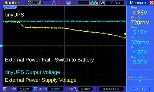
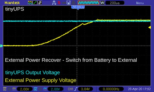
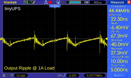
Figure 4 shows the oscillogram of the TinyUPS output voltage when the external power source is disconnected and switches to battery. Channel 1 (yellow) - external power supply voltage, channel 2 (blue) - UPS output voltage. Figure 5 is a waveform of the TinyUPS output voltage when the external power source is turned on (switching from backup battery to external source) .The output voltage ripple at 1 A output current is shown in Figure 6.
| Table 2. | TinyUPS Technical specification. | ||||||||||||
|
|||||||||||||
 |
||
| Figure 4. | TinyUPS output voltage when the external power source is disconnected and switch to battery | |
 |
||
| Figure 5. | TinyUPS output voltage when the external power source is turned on | |
 |
||
| Figure 6. | TinyUPS Output voltage ripple at 1 A output current. | |
Notes
The EP plate of the FP6277 requires a good conductive connection to the corresponding plate on the PCB.
References
- Project page on github.com
- Designing A Li-Ion Battery Charger and Load Sharing System
- TinyUPS project in EasyEDA