Andy Collinson
Description
An electromagnetic field probe designed to detect changing electric and magnetic fields. The probe has switchable gain, a frequency response up to 400kHz and independent audio and meter monitoring.
Circuit Notes
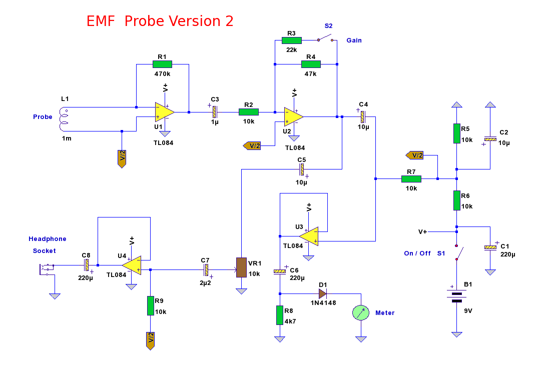
This EMF probe uses an inductor to locate stray electromagnetic (EM) fields. It will respond to both changing magnetic and electric fields as each will induce a voltage in the inductor. The circuit is built around a quad low noise FET input op-amp, type TL084.
Power supply is a single 9 Volt battery, the supply being divided by R5 and R6. C1 and C2 help smooth variations in battery voltage, S1 is the on off switch. The input stage U1, is direct coupled to the probe, a radial wound 1mH inductor, type Toko 8RB as shown in the probe construction. This part appears only available from Jabdog Electronics in the UK, part number 187LY-102J. If not available then the 1.2, 1.5 or 1.8mH inductor will work equally well. The reactance of the inductor changes with input frequency and stage gain is very high. As there is no offset null control in the TL084 then the output is capacitively coupled via C3 to the next Tl084 amplifier U2. This stage has switchable gain of approximately 1.5x and 4.7x controlled by S2.
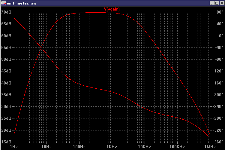
The output gain of both U1 and U2 stages ( with switch S2 open ) is about 70dB at 1KHz. Gain is still about 30dB at 400KHz, although the signal meter will not be too accurate at such high frequency. The bode plot simulated in LTspice is shown below:
The output from U2 is split by C4 and C5 and drives an independent headphone amplifier built around U4. VR1 acts as a volume control the output being either a mono or stereo miniature jack plug as shown. The output stage of the TL084 is sufficiently low to drive 32 ohm headphones like Sennheiser or Ipod Shuffle, etc. U3 is the meter amplifier. All EMF fields are amplified across the load resistor R8. D1 now acts as a half wave rectifier and creates sufficient DC voltage to drive a small signal meter, shown below.
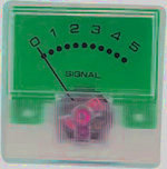
This signal meter is available from Maplin Electronics part number LB80B and has a FSD of 250uA and an internal resistance of 675 ohms. However any meter will work having a similar sensitivity. Meters of 100 or 50uA FSD can also be used providing a suitable series resistor is used. Because the circuit is responding to RF frequencies up to several hundred kHz a smoothing capacitor across the meter should not be used as this would appear as an effective short circuit reducing the average current through the meter to zero.
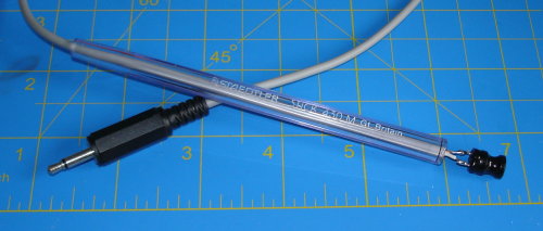
Probe Construction
The probe is made from an old pen tube, the end cap being removed. A 50cm length of audio screened cable is threaded through the pen tube and soldered to the radial inductor. The capacitance of 50cm audio cable is about 2pF, longer cable should not be used as high frequency performance will deteriorate.
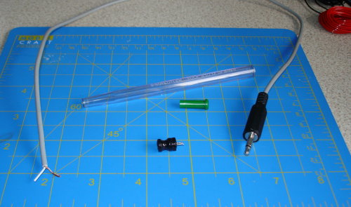
The cable may be used with a 3.5mm mono plug and socket if desired. My completed probe is shown below. The diameter of the inductor fitted neatly against the body of the pen tube. A layer of insulating tape or glue may be used to secure the pen body to the inductor.
To be continued