Simulation Model
To model this circuit in LTspice or any other simulator you have to take into account the input capacitance of the probe cable, and the impedance of the inductor itself. The cable capacitance was measured by a capacitance meter and came out at 1.9pF, so 2pF was added in parallel with L2 which is the probe inductor. The simulation schematic is shown below:
The Toko 8RB inductor has a series resistance of 7 ohms, at 100kHz the impedance is 628.3 ohms. The series resistance of L2 needs to be included, in LTspice the inductor L2 can be right clicked and a value for series resistance entered, or as shown above can be entered in the value of Rs. A transient response at 10kHz is shown below:
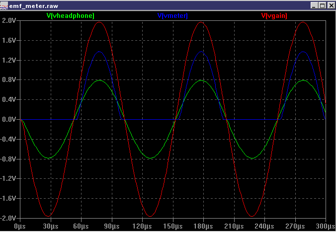
The simulation model has 3 nodes labeled Vgain, Vheadphone and Vmeter for clarity. These waveforms are shown above. The input has been simulated by a signal generator feeding another coil. The coupling coefficient of 0.9 is used and input voltage of 10mV pk-pk used.
Download Simulation Circuit
The simulation circuit for LTspice can be downloaded here. Please note that you will also have to download the model for the potentiometer and TL072 op amp from the LTspice yahoo group, more details in the simulation section. The TL072 simulation model is the same as the TL084 model.
Testing
If you have access to an audio or RF signal generator you can apply an input signal to the windings of a small transformer or another inductor. This will set up an electromagnetic field which will be easily detected by the probe. Without a signal generator, just place the probe near a power supply, mains wiring or other electrical device. There will be a deflection on the meter and sound in the headphones if the frequency is below 15KHz.
Parts List
|
IC1 |
|
|
D1 |
|
|
L1 |
1mH radial inductor part 187LY-102J |
|
R1 |
470k |
|
R2, R5, R6, R7, R9 |
10k |
|
R3 |
22k |
|
R4 |
47k |
|
R8 |
4k7 |
|
VR1 |
10k log |
|
C1, C6, C8 |
220u |
|
C2, C4, C5 |
10u |
|
C3 |
1u |
|
C7 |
2.2u |
|
Signal meter 250uA FSD, |
In Use
Switch on, set VR1 to minimum and plug in headphones (optional). The circuit can be built on veroboard and is designed to be portable. Try moving the probe near a light switch or electric socket and a loud hum will be heard in the headphones and meter will deflect.