Description
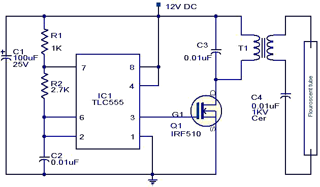
Here is a simple and effective circuit for driving florescent lamps from a 12 V supply. The circuit is nothing but consists of an oscillator, a MOSFET switch and a step-up transformer for driving the florescent lamp.
The IC1 TLC555 is wired as an astable multivibrator for producing the necessary oscillations. The MOSFET Q1 is used to amplify the oscillations produced by the IC1. The out put of MOSFET is connected to the primary of the step up transformer to produce a ~400 V AC for driving the florescent lamp.
Circuit diagram with Parts list

Notes
- C3 and C2 must be 25V ceramic capacitors.
- C1 must be electrolytic.
- For T1, use a 10W, 230V to 10V step down transformer in the inverted configuration. That is 10V winding must be connected to the MOSFET side and 240V winding must be connected to florescent lamp side.
- Use a 12V lead acid battery for powering the circuit.
- It is better to fix a heat sink to Q1.
- The florescent lamp can be of a 4W one.