Francois DRUILHE - francois.druilhe free.fr
The purpose of this project is to develop a self sufficient Mailbox (real one) that will be powered only by the sun and that will display the number of the house, but only in accordance with the battery level. The system must work autonomously when there is or not enough light to charge the battery.
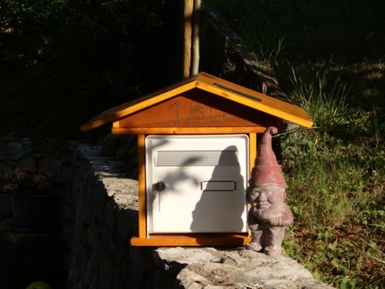
Final external Realization
The Mailbox is powered by a 5V/80mA Polysilicon solar cell. The sun energy is used to charge a 3 AA NiMH battery. At night, when there is no light, the PIC is driving the 3 Digit according with a sequence which is defined in its program given in Annex.
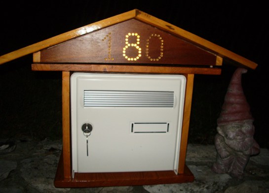
At night: Central Digit On, other one in PWM Modes
Schematic Explanation

Charger_Control: The Solar Cell is charging the 3 AA NiMH cell trough the “Sziklai pair” composed by the T5 (2N2907) and T4 (1N1711). This is necessary to ensure a very low reverse current when the sun is off and the battery at full charge. Control of the charge can be applied on D5 with a "1" level from the PIC , which will reverse the T6 that define the current in T5 base. For Battery protection purpose, the value of Zener diode DZ6 must be 4.6V to prevent the battery for over-charging which will degrade significantly its life time. This function is not yet managed by the PIC program and is reserved for further use.
LED_OR_control: The 3 digits are controlled by 3 separate 2N1711 (each digit is compose about 20 white LED). The control signal is the OR between a PWM signal, that ensure a constant background level of light plus a "blinking" part which is the sequence generated by the PIC.
Sun_Sense: Just a low pas filter composed of R8 and C6. Beware that leakage current from the PIC can affect the level. This prevent R8 to be bellow 39KOhms.
Vbat_sense: These 2 diodes in serial create a 1.3V constant voltage that can be measured by the PIC to determine the level of the battery. This function is not yet managed by the PIC program and is reserved for further use.
Cpu: The PIC16F628 operates with a 32.768KHz crystal oscillator. This frequency have been selected, not to consume too much. In this condition, the PIC is able to operate down to 3V.
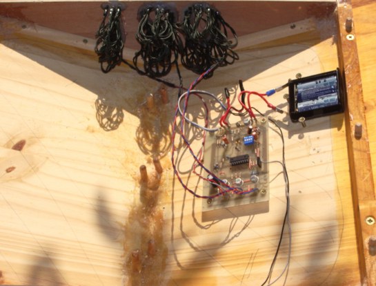
Internal Wiring
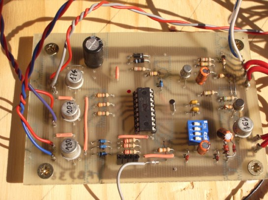
PCB zoom
Behavioral Explanations
Apart when the Battery is totally low, the PIC is running and infinity loop which period is approximately 1 second, the red led is blinking accordingly.
During day light the SunSense signal is high and the PIC is not performing any operation (than the 1 second blinking loop). The Green led is on. If the battery voltage is low enough, the Solar cell is charging it. If the Battery voltage is above 4.6V (3 times 1.3V), then the DZ6 is drawing the current to ground protecting the battery cells. In the future Vbat_sense and Stop_Charge should be used.
During night the SunSense signal get low and the PIC is programmed to:
- Generate a PWM signal (100Hz, Duty Cycle of 5%) on the PWM pin
- Generate a "blinking" sequence on the 3 separate control signals (1 minute period)
PIC Source Code
// --------------------------------------------------------------------------------------
//
// Boite aux Lettres
//
// (C) F. Druilhe 30 Juillet 2009
//
// --------------------------------------------------------------------------------------
#include
// Define Crystal Oscilator frequency
#define _XTAL_FREQ 32768UL
// Configure the Chip
__CONFIG(LP & WDTDIS & PWRTDIS & BORDIS & LVPEN & UNPROTECT);
// ------------------- Global Variables -----------------------
#define LED_SEQ 60
unsigned char led_count; // Led Counter
unsigned char program; // Number of sequence to execute
unsigned char sec_count; // Second counter
unsigned char min_count; // Minute counter
unsigned char hour_count; // Hours counter
unsigned int day_count; // Day counter
unsigned char sun_rise; // First sun variation
// ----- Local Working variables
char c, d; // Local Variables
// Led Sequence
char led_table[LED_SEQ] = {/* "8", "O", "1", void */
0b0000, 0b0010, 0b1010, 0b1000, 0b1000, 0b1100, 0b0100, 0b0000, 0b0000, 0b0000,
0b0000, 0b0010, 0b1010, 0b1000, 0b1000, 0b1100, 0b0100, 0b0000, 0b0000, 0b0000,
0b0000, 0b0000, 0b0000, 0b0000, 0b0000, 0b0000, 0b0000, 0b0000, 0b0000, 0b0000,
0b1110, 0b1110, 0b1000, 0b1000, 0b0110, 0b0110, 0b1110, 0b1110, 0b0000, 0b0000,
0b0000, 0b0000, 0b0000, 0b0000, 0b0000, 0b0000, 0b0000, 0b0000, 0b0000, 0b0000,
0b0010, 0b1000, 0b0100, 0b0000, 0b0100, 0b1000, 0b0010, 0b0000, 0b0000, 0b0000
};
// Initializations
void initPORT(void)
{
// Port A: RA0: Vref_in
// RA1: L3Ctrl_out
// RA2: L1Ctrl_out
// RA3: L2Ctrl_out
// RA4: nc
// RA5: MCLR input
// RA6: Osc
// RA7: Osc
TRISA = 0b11110001;
// Port B: RB0: CellSence_in
// RB1: Rx_in
// RB2: Tx_out
// RB3: PWM_out
// RB4: Conf0_in
// RB5: Conf1_in
// RB6: StopChrg_out
// RB7: GLedCtrl_out
// port directions: 1=input, 0=output
TRISB = 0b00110011;
// Option: PS: 000
// PSA: 0 assigned to Timer0
// T0SE: 0 faling edge
// T0CS: 0 internal clock
// INTEDG: 1 rising Edge (sunshine)
// nRBPU: 1 pull-ups disable
OPTION = 0b11000000;
// Set the Port to off
PORTB = 0b00000000;
PORTA = 0b00000000;
// Program PWM frequency is 100Hz with a ratio is 5%, active high
// PR2: 0x51 (81); Freq = 32768/4/(PR2+1) = 99.9024 Hz
PR2 = 0x51;
// CCPR1L: 0x8 (16/4); FreqOn = 32768/(PR2+1) = 2000Hz
CCPR1L = 0x4;
// CCP1CON: CCP1X: 0 Lsb
// CCP1Y: 0 ..
// CCP1M3..0: 1110 PWM active high
CCP1CON = 0x0E;
// T2CON: T2CKPS1..0: 00 Predividor by 1
// TMR2ON: 0 Off
// TOUTPS3..0: 0000 Postdividor by 1
T2CON = 0;
}
#define enable_PWM T2CON = 0b00000100
#define disable_PWM T2CON = 0b00000000
void initVAR()
{
// Init Variables
program = 0;
led_count = 0;
sun_rise = 0;
// Init Time
sec_count = 0;
min_count = 0;
hour_count = 0
day_count = 0;
}
// Main
void main(void)
{
initPORT(); // Init platform Ports
initVAR(); // Init Variables
while (1){
PORTB = 0b10000000; // Set Green Led on
__delay_ms(100); // small delay
PORTB = 0b00000000; // Clear Green Led off
//------- Read Sun Level
c = PORTB & 0b00000001;
if (c) {
//----------- Sun raise: reset everything
led_count = 0; // Reset Led Counter
sun_rise = 0;
PORTA = 0b00000000; // Clear all Led Bits
disable_PWM;
} else {
//----------- Sun fall: light on Leds
if (!sun_rise) {
enable_PWM;
sun_rise = 1;
}
// Execute the current led sequence
c = led_table[led_count] & 0b00001110; // Get the sequence in the table
// and mask in case
PORTA = c; // Set leds
led_count++; // Increment the Led Counter
if (led_count >= LED_SEQ) led_count = 0; // Reset led sequence
}
//---------------- Complement to 1 second --------------------
__delay_ms(900); // one second
//------- Increment overall time
sec_count++;
if (sec_count >= 60) {
sec_count = 0x0;
min_count++;
if (min_count >= 60) {
min_count = 0x0; // Hours not manged yet
hour_count++;
if (hour_count >= 24) {
hour_count = 0;
day_count++; // Increment Day
}
}
}
}
}