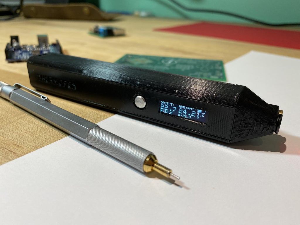
Also called the ThermoPen, the goal of this project was to create a portable thermometer usable for precise uses case. More particularly, is was created to inspect overheating electronic parts on PCB and for general troubleshooting. At my school, the ThermoPen was a highly requested product, as multiples teachers who get in touch with electronics need a tool for fast troubleshooting with projects from students or themselves (Figure 1).
So how exactly this weird pen works? Is it only a simple temperature infrared sensor glued onto a pen? To be clear, the pen features an Ir sensor that converts infrared emission from objects into an electric signal which can be translated to a temperature by a micro-controllers.
In that way, I made a PCB that integrates an Atmega 328P (same controller as the Arduino Uno/Nano) to control inputs and outputs from buttons and sensors. In its simplest expression, it's an Ir sensor that reads temperature. What makes the ThermoPen different and original from this basic concept is that it includes features extremely useful for the user, in a small and slim form factor.
 |
||
| Figure 1. | ThermoPen – Infrared Thermometer Pen. | |
The ThermoPen features:
- An OLED screen that displays objects temperature, ambient temperature, maximum and minimum object temperature
- Audio feedback
- Press-to-activate button
- Rechargeable Li-Ion battery circuit
- Laser diode acting as a pointer
All project files available on download section and on Github repositories [1].
Overview of the Project
Before starting building the infrared thermometer, it's important to understand how it works (Figure 2).
To begin with, the ThermoPen is built around a custom-made PCB that integrates an Arduino-like circuit. It takes inspiration from the Arduino Nano circuit for the integration of the ATmega328P micro-controller and from the circuit of an Adafruit Arduino Uno shield for the charging of a ŀi-Ion battery.
 |
||
| Figure 2. | ThermoPen Block Diagram. | |
When pressing the button, the battery is powering the circuit and the program inside the micro-controller starts its initialization. A Power-up sound is made. After 1 second, the laser diode goes ON and the screen prints real-time data read from the thermometer sensor. The Arduino code also calculates min and max temperature, as well as battery voltage and capacity. Releasing the power button will let the ThermoPen to work for 4-5 seconds before turning off, made possible by capacitors.
To be clear, the laser diodes only purpose is to give the user an idea of where the temperature is measured. The true magic is made possible by the temperature sensor MLX90614 made by Melexis, which uses a physics principle where an object will emit a certain quantity of infrared light depending on its temperature. From there the sensor converts the quantity of infrared wavelength received into an electric signal proportional to the temperature which is processed by the micro-controller into a temperature in Celcius.
The PCB have different optional LED that can be soldered ON. One will indicates when the battery is too low. The battery icon will also start to blink in that condition. Fortunately, the pen includes a micro-USB connector with a Li-ıon battery charger circuit, so it's not necessary to charge manually the battery.
Design the Schematics and the PCB
As I said earlier, the schematic takes inspiration from the Arduino Nano for the Atmega328P circuit including its power circuits and clock choices (Figure 3). For convenience, I took a crystal generating a lower frequency, as it would enhance batter efficiency. The Oled screen, buzzer, IR sensor, and laser diode are connected to the micro-controller, via Analog pin, Digital pin, or from I2C communication bus. For the circuit related to the charging and discharging of the Li-Ion battery, I took some serious inspiration from an Adafruit Arduino Uno shield for a rechargeable battery [2].
 |
||
| Figure 3. | ThermoPen Shematic Diagram. | |
Everything was done using KiCad and some libraries provided by DigiKey, a big electronic parts retailer. You will find the complete KiCad project in the download section and ThermoPen GitHub [1].
I used KiCad for Schematics design, as well as PCB design. It's a really powerful software for an open-source project, and it's free.
During PCB design, I also took time to select the right electronics parts that fitted my use case. For example, I had to select a small package size so it would fit inside a small enclosure. Most resistors and capacitors are 08x05 package size.
Product Design and 3D Render
The 3D design was done using Solidworks.
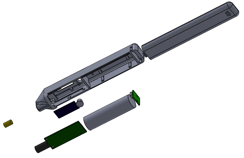
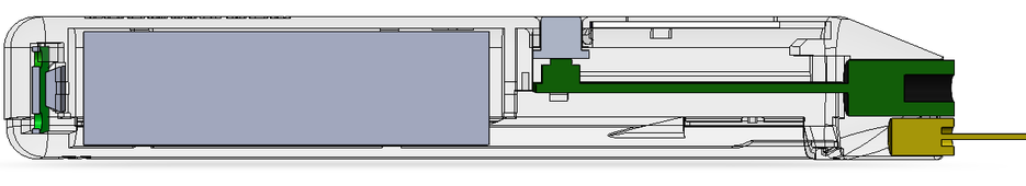
To make my life easier, I modeled all the parts I knew the dimension, like the battery, the USB connector, the PCB, the diode laser, and the infrared sensor (Figure 4).
I decided to choose a squared shape, so I could easily pass wire around the battery or other components. I wanted the tolerance to be very tight, so no screws would be used. As a result, the battery clips very nicely in the casing, as well as the PCB. For the button, I made a clever design that integrates an aluminum button that is squeezed between the PCB button on the plastic housing.
 |
||
 |
||
| Figure 4. | Case for ThermoPen and 3D Render. | |
The laser diode is placed just between the IR sensor for maximum accuracy. When the product is in the hand, the laser is hidden behind the point of the pen. It's a more elegant way to integrate the laser because it seems to the user that the laser comes from the IR sensor, but it's not.
On the main side of the pen, I placed the Oled screen next to the button and the ThermoPen Branding at the other end. On one side, there are two holes for the charging indicator LED, which indicate when the battery is charging and fully charged.
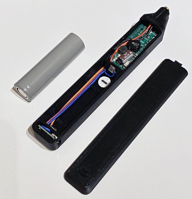
As you see, the inside is accessible by a sliding cover dissimulated at the backside of the pen. It stays in place by a plastic bracket. The assembly is done on this side and is also used for battery replacement (Figure 5).
 |
||
 |
||
| Figure 5. | Assembling the ThermoPen. | |
Soldering of the PCB
One of the greatest challenges of the project was to solder every part without any failure, as the PCB contained more than 50 parts that required different soldering techniques and equipment.
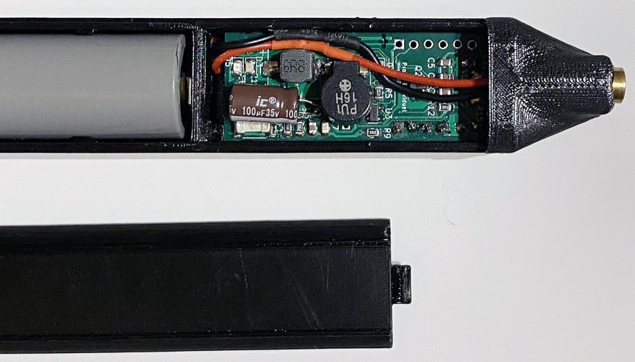
Firstly, I designed the PCB so all components that requires a reflow oven are located on the same side. It was the case for the Atmaga 328P, as well as the buck-boost circuit that converts 3.7 V from the battery to 5 V for the micro-controller (Figure 6). For better tin application, I used an electronic magnifying glass with a Timed Air Dispenser filled with tin.
 |
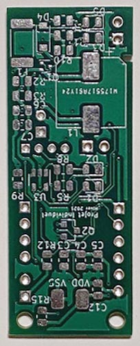 |
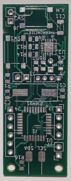
| Figure 6. | Printed Circuit Board for ThermoPen. |
he buck-boost chip caused me some serious trouble, as all of its pads were underneath the package type. As a result, my first soldered PCB got burned because of a short circuit caused by this chip. It to me some time to find the problem, which caused me to reconsider the quality of the electrical wiring. Fortunately, I fixed this problem by soldering a new PCB and from now on the circuit seemed to react normally when powered.
You will notice that the PCB includes lots of connector holes. This is where the wires for different components located outside the PCB will be soldered on the assembly step.
Programming of the Microcontroller
The Arduino code file is available in the download section and ThermoPen GitHub project.
I will not explain in detail what's in my code, as it remains a fairly simple one.
Its general content is:
- Multiple libraries for the Oled screen, display graphics, and infrared sensor.
- A setup sequence doing a startup sound and initializing the laser diode and Infrared sensor.
- Read and print battery life.
- Print object temperature, ambient temperature, minimum and maximum temperature.
To program the Atmega 328p, I considered the ThermoPen like it was another Arduino Uno/Nano. Using an SPI connection between our PCB and another Arduino, called the host, I could program my soldered chip using a method called "Arduino as ISP". The Arduino ISP is an In-System-Programmer that is used to program AVR microcontrollers [3].
Also, I tried to include a sleep mode so the TermoPen goes to sleep when activated for too long to prevent battery discharge, but I didn't succeed to make it work. For now, it works well without this functionality and I"m fine with it.
These result depend only on the sensor, as the manufacturer says that they are calibrated at the factory.
I also tested the over-temperature alarm, where the buzzer makes a sound when passing a temperature threshold (set at 120 °C).