In addition to the traditional lead-acid battery, modern electric/hybrid cars often include a large capacitor (40 F or more) as a backup power source. Located under the rear seat, this capacitor ensures an extra 10 to 15 minutes of driving time that allows you to reach the next charging station or gas station. Lead-acid batteries discharge down to only 8 V or so, but a capacitor can discharge all the way down to 0 V. This capability requires a current-sense amplifier that can measure inputs to 0 V.
Most high-side current-sense amplifiers, however, operate over a limited range of common-mode input and supply voltages. Consider, for example, the MAX4081, whose common-mode input and supply voltages range from 76 V down to 4.5 V. To set a zero load-current point (that is, the voltage output corresponding to zero load current, where VSENSE = 0 V) for a bidirectional (charge/discharge) current-sensing application, one normally connects an external reference (+2.5 V, for instance) to the reference input (REF). For the MAX4081, the lower common-mode limit of 4.5 V normally prohibits its use in applications that require current sensing close to ground.
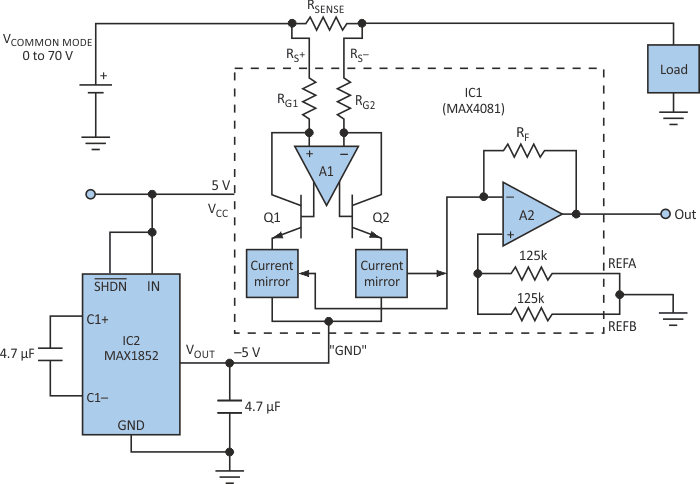
Designers can solve this problem by connecting a charge pump to the circuit (Fig. 1). The tiny charge pump (IC2) is powered from +5 V, as is the current-sense amplifier. The output of the charge pump (–5 V) acts as a negative supply voltage at the "GND" pin of IC1. REFA and REFB of IC1 are connected to the circuit GND.
 |
|
| Figure 1. | Using a charge pump to add a 25-V rail to this current-sense amplifier extends its lower common-mode limit from 4.5 V down to 0 V. |
The internal op amp (A2) of IC1 now operates from 65-V rails (a 10-V span), with its non-inverting input (REF pins) sitting at the 0-V mid-rail level. For VSENSE = 0 V, the output voltage is 0 V. VSENSE then increases with load current, producing an output of 5X, 20X, or 60X, according to the part number's gain suffix – F, T, or S. The effective common-mode range now extends from 0 V to +70 V, with the original specifications unchanged (VOS < 0.6 mV, and gain error < 0.6%).
Tests on the circuit in Figure 1 showed that the current-sense amplifier's common-mode voltage (with "GND" connected to 25 V) can go down to 22.8 V. In contrast, common-mode voltage for the standard application (with GND connected to 0 V) can go down only to +2.3 V. With REFA and REFB shorted to GND, however, the output can swing 5 V above and below GND.
IC1's typical supply current (103 µA) presents a small load current to IC2, which prevents overloading and voltage drooping at its output. Take care when the output moves below GND. Load current then flows out of IC1's GND terminal and into the charge pump, whose negative output can droop as a result (rise toward 0 V). As a countermeasure, you can use bigger capacitors in the charge pump or restrict the sense amplifier's output voltage.