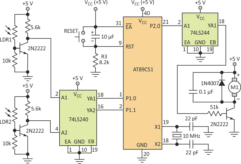
This 8051 microcontroller-based control circuit adjusts the speed of a small permanent-magnet dc motor via photosensors (Figure 1). The circuit can find applications in light-tracking systems for adjusting tracking-motor speed depending on the intensity of the incident light. It can also be modified to control more than one motor at the same time.
The circuit and software varies the speed of the motor in three levels, depending on two photosensors connected to the microcontroller. The microcontroller input port (Port 1) senses the voltage level of each photosensor circuit, while the program stored in the microcontroller’s memory produces the necessary PWM signal at its output port (Port 2) to drive the motor circuit.
 |
|
| Figure 1. | This dc motor speed-control circuit uses standard, available components; light impinging on two independent photoresistors establishes the motor's speed. |
Motor speed can be adjusted by the light intensity falling into the photoresistors LDR1 and LDR2. These resistors control the bias points of two transistors connected via an input inverting buffer (74LS240) to Port 1 of the AT89C51. The base and collector resistors of the photosensor circuit were chosen empirically to properly set the transistor in cutoff and saturation regions. The output signal from Port 2 of the microcontroller is delivered to the motor circuit with the aid of a non-inverting buffer (74LS244).
When there’s no light incident on either of the LDRs, its resistance will be large (reaching to approximately 1 MΩ) and thereby turning the transistor off. In this case, the collector voltage of this transistor will be high (+5 V). On the other hand, when the light brightness increases on the photoresistor, its resistance will decrease to about 1 kΩ at full-light illumination, thereby causing the NPN transistor (2N2222) connected with it to switch on. In this case, the collector voltage of the transistor will be low.
The inverting buffer (74LS240) is used to invert the signal levels at the nodes of the transistors’ collectors. When either of the two transistors is on, the signal at the input of the respective buffer (A1 or A2) is at logic 0 (grounded), and in this case, the buffer output (YA1 or YA2) is high. On the other hand, when the transistors are off, the corresponding output of the buffer is low. This buffer is also used to protect Port 1 of the 8051 microcontroller.
The 74LS244 buffer protects Port 2 of the 8051 microcontroller from the motor circuit and provides sufficient current to drive the output transistor. The dc motor is connected to a +5-V dc supply via the driving transistor. And a free-wheeling diode is connected across the dc motor to protect the transistor from any back-induced voltage. The capacitor in the motor circuit removes the EMI and noise produced during motor operation.
When the output signal from pin P2.0 is set HIGH (Logic 1), current passes through the buffer and the base of the driving transistor. This turns on the driving transistor and the dc motor. The signal generated at pin P2.0 is a pulse-width-modulated waveform to control the average voltage provided to the motor, by controlling the switching-on time of the driving transistor. The control program stored in the memory of the 8051 microcontroller generates this signal. The control program is available for download in the Loading section.
The control program was converted into a hex machine-code file using the ASEM-51 assembler, and then burned into the flash memory of the AT89C51 using a commercial universal programmer. The selection of the required speed is achieved by controlling the light falling on LDR1 and LDR2 (Table 1).
| Table 1. | DC-motor speed levels | ||||||||||||||||||||
|
|||||||||||||||||||||
Port 1 is defined as an input port, while Port 2 is left as an output port. The received signal from Port 1 is masked with the binary number 00000011 using the ANL logic instruction, to check the value received by Port 1 depending on the states of the photosensors. This value is compared with 00, 01, 02, and 03, respectively, to send the appropriate PWM signal into the motor circuit. A delay subroutine is included to produce the necessary delay times for the required PWM signals.
Materials on the topic
- Datasheet Microchip AT89C51
- Datasheet Texas Instruments SN74LS240
- Datasheet Texas Instruments SN74LS244