You use limit switches to switch off a motor if it reaches one of its two end positions. Even if you build a microprocessor-based motor controller, you should switch off a motor with hardware by building a safety interlock. Such a circuit works by inhibiting movement in one direction but allowing movement in the other direction when the motor retracts from its end position. Figure 1 shows the circuit with mechanical switches. However, this ancient mechanical approach may be unsuitable in some cases because the motor current may be too high, or the switches may be closing switches or light barriers.
 |
|
| Figure 1. | This circuit works by inhibiting movement in one direction but allowing movement in the other direction when the motor retracts from its end position. |
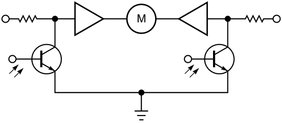
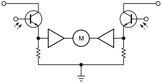
If you use an H bridge to drive the motor, you can achieve the same operation in a more versatile way. The circuit in Figure 2 shortens one input of the H bridge to ground so that movement is possible only in the other direction by turning on the other input. If the switches are opening at the end positions, the circuit in Figure 3 interrupts the connection to the driving circuit of one input and sets the input to low using a pulldown resistor. The same circuit works with phototransistors without modification (figure 4 and figure 5). The value of the resistors depends on the parts you use; a value of 10 kΩ should work in most designs.
 |
|
| Figure 2. | This circuit shortens one input of the H bridge to ground so that movement is possible only in the other direction by turning on the other input. |
 |
|
| Figure 3. | This circuit interrupts the connection to the driving circuit of one input and sets the input to low using a pulldown resistor. |
 |
|
| Figure 4. | This circuit is the same as that in Figure 3, and it works with phototransistors without modification. |
 |
|
| Figure 5. | This circuit is the same as that in Figure 4; the value of the resistors depends on the parts you use. |