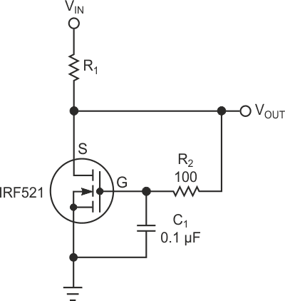
You would normally use a series linear regulator or a dc/dc converter to obtain 3 V dc from a higher supply. However, when breadboarding a concept, you may be able to use a shunt regulator, especially if a series regulator of the correct voltage is unavailable. The MOSFET in Figure 1 can replace a zener diode in a shunt regulator and provide lower output impedance than a zener diode.
 |
|
| Figure 1. | A MOSFET configured to replace a zener diode of a shunt regulator provides lower impedance than a diode-based implementation. |
The MOSFET is self-biased by connecting its drain to its source. The difference between the input voltage, VIN, and the gate-to-source threshold voltage, VGS, sets the current. The IRF521 in this example has a threshold voltage of 2 to 4 V at 250 µA. The upper curve of Figure 2 shows that the IRF521 achieves a gate-to-source voltage of 3 V at a current of about 200 µA. MOSFETs can vary from device to device, but the typical MOSFET has a threshold at approximately the mean between the maximum and the minimum limits.
The lower curve in Figure 2 is the output impedance, which you obtain from the upper curve by differentiating the upper curve. Although the output impedance, ROUT, is near 800 Ω at a current of 100 µA, it rapidly drops to less than 6 Ω at 50 mA. Because you operate the MOSFET at or near threshold, its on-resistance spec doesn't apply, and the output impedance of this circuit is far higher than you would expect from the on-resistance. However, in general, the lower the on-resistance, the lower the output impedance at a specific current near threshold.
 |
|
| Figure 2. | A plot of key parameters – gate-to-source voltage and output impedance –versus drain current shows smoothness of variation over two and one- half decades. |
This circuit may require that R2 and C1 stop the oscillation in the MOSFET. Add a filter capacitor to the output to minimize the effect of load transients. Connecting a large filter capacitor from the gate to the source with short leads eliminates the need for R2. You can use other MOSFET families and other voltages if necessary.
Although you may be unable to get the exact output voltage you need at the current you prefer, many devices tolerate wide variations in operating voltage. For instance, many 3.3 V-dc microcontrollers can operate as low as 2.5 V dc and as high as 3.6 V dc. Note that operating a MOSFET near its threshold causes a large negative-temperature coefficient of the gate-to-source voltage. This circuit has significant change in output voltage over a wide temperature range; it is suitable for only limited temperature ranges.