This project provides AC voltage zero-cross timing detection and a DC voltage after diode rectification with high accuracy. Possible applications for such circuits are AC motor controllers, AC lamp controllers, AC Dimmer Controllers, Home Appliances. The circuit outputs a zero-cross signal from 90 Vac to 264 Vac input. The project is based on BM1Z102FJ chip which outputs a high precision zero-cross timing of targeted AC voltage and a DC voltage after diode rectification of high accuracy. The project also includes high voltage offline AC to DC converter chip BM2P129TF.
AC voltage zero cross detection
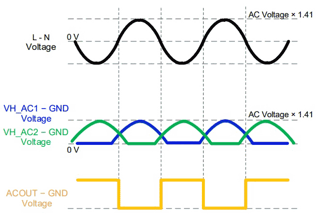
By monitoring the voltage between the VH_AC1 and VH_AC2 pins, this IC outputs the zero-cross point of AC voltage from the ACOUT pin. These pins have a built-in monitor circuit that tolerates 600 V and they realize high reliability and low power consumption. The ACOUT pin performs an N-channel open-drain output and this makes it possible to support various applications. It is necessary for the VH_AC1 pin to be connected to the N side of the AC input and for the VH_AC2 pin to be connected to the L side of the AC input.
Note:
The circuit operates with potentially lethal voltages, it is advisable to use an isolated probe for measurement using an oscilloscope
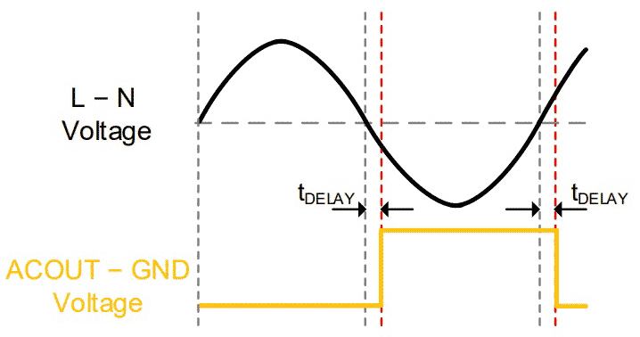
Output delay setting (DSET pin setting) – resistor R7
- R7 OPEN DELAY 0 µs
- R7 330K 200 µs
- R7 68K –200 µs
- R7 0 OHMS –480 µs
DCOUT Pin 4
- 110 V AC Outputs 1.1 V DC
- 230 V AC Outputs 2.3 V DC
Safety note
This board works with mains high voltage contains lethal voltage and should be handled only by qualified personnel familiar with all safety and operating procedures. Board contains parts that store significant charges even after disconnecting from the power source. Please discharge the capacitors after using the board, and please deal with it after confirming such electric discharge.
Be careful to not allow conductive objects to come into contact with the board. DO NOT touch the board with your bare hands or bring them too close to the board. In addition, as mentioned above please exercise extreme caution when using conductive tools such as tweezers and screwdrivers.
 |
|
| Figure 1. | Input-output waveforms. |
Features
- Supply Input 90 V AC to 264 V AC
- On Board AC to DC Offline Converter (90 V AC-264 V AC input, 12 V DC Output @ 100 mA)
- DC Output about 1/100 voltage Approx. 1.1 V with 110 V AC, 2.3 V with 230 V AC input
- Input Frequency Response 47 Hz to 63 Hz
- Provides Accurate 50 Hz Square wave with 230 V/50 Hz AC Input
- Default Output Pulse Delay time = 0 µs (Can be Adjust Using R7)
- Aux DC Supply Output VCC-12 V and 5 V DC @ Maximum Load 100 mA
- PCB Dimensions 58.90 × 28.73 mm
Schematic
 |
|
| Figure 2. | Schematic of the AC VOLTAGE ZERO CROSS DETECTOR. |
Connections
 |
|
| Figure 3. | Connections. |
Application circuit
 |
|
| Figure 4. | Typical application circuit. |
Waveforms
 |
|
| Figure 5. | DCOUT pin Voltage vs VH_DC Pin Voltage. |
 |
|
| Figure 6. | Zero cross delay. |
 |
|
| Figure 7. | Output waveform. |
 |
|
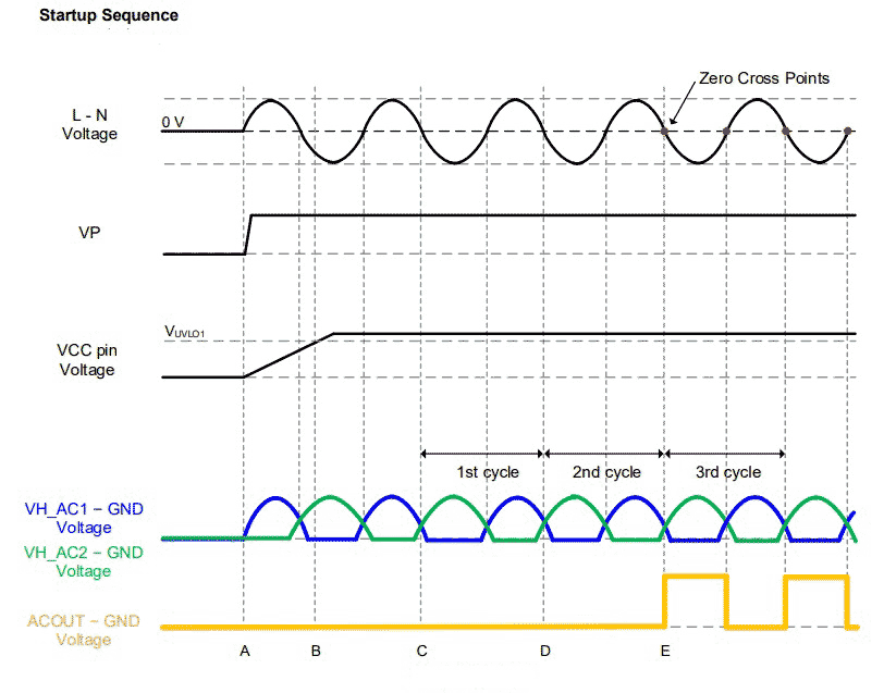
| Figure 8. | Start sequence. |
Photos
 |
|
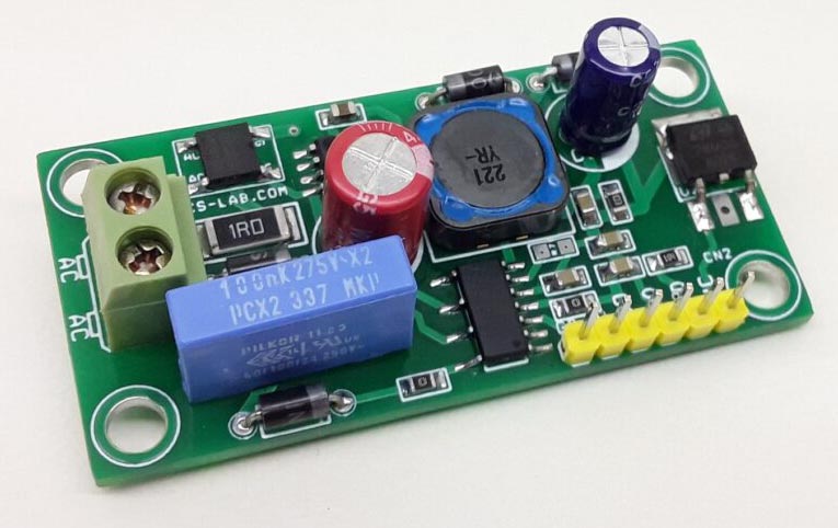
| Figure 9. | Upper side of the board. |
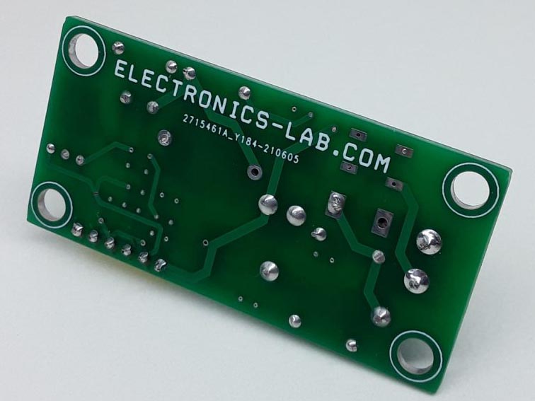 |
|
| Figure 10. | Down side of the board. |