To measure a zener diode’s breakdown voltage, you need a dc voltage source whose voltage exceeds that of the zener voltage. In Figure 1, resistor RSER provides voltage drop between VIN and VZEN. In any case, VIN should exceed VZEN. Resistor RSER must provide current, IZEN, that can keep the zener diode in reverse breakdown. That is, the current must be more than IZEN – IZENMIN and less than IZEN – IZENMAX. You also need to consider the current that flows through the load. Otherwise, VZEN will be unregulated and less than the nominal breakdown voltage. Also, the power that the zener diode dissipates should not exceed the manufacturer’s specifications. Except for the value of IZEN – ZENMIN, all necessary data appears in zener-diode data sheets.
 |
|
| Figure 1. | Current through a zener diode creates a fixed voltage across the device. |
The circuit in Figure 2 uses one or two AA/AAA cells, which ensures testing irrespective of the value of the tested zener voltage to approximately 20 to 25 V. The heart of the circuit is a Zetex LED driver, ZXLD381. It operates mainly from 1.5 or 1.2 V cells, and it has a maximum input voltage of 10 V. The LED driver generates constant-power pulses that charge output of the 10-μF capacitor, which requires low leakage current. The capacitor’s voltage provides constant current through R1 and the zener diode that connects in series. When you connect output probes to a digital multimeter’s V and COM sockets, you can directly measure the zener’s voltage when the S2 switch is in the position Figure 2 shows.
 |
|
| Figure 2. | An LED driver provides current for the LED under test. |
When S2 is in the upper position, the meter measures voltage across R1, a 1-kΩ resistor; the meter displays a negative-voltage-drop value. R1’s value ensures direct reading of the meter; the voltage drop across R1 corresponds to the zener’s current, so there is no need to switch over DVM (digital-voltmeter) ranges. R1’s voltage drop limits the zener diode’s voltage value that the circuit measures. If R1’s value is 1 Ω, then the voltage drop across it is insignificant and, in millivolts, is equal to the zener diode’s current in milliamps.
If you need to measure zener-diode voltage higher than 20 to 25 V, you can add an LED driver (Figure 3). When the S2 switch is in the upper position, both LED drivers connect in series, and you can measure zener voltage to approximately 40 V at 0.7 mA. With S2 in the lower position, both LED drivers connect in parallel, and the tested zener voltage is approximately 20 to 25 V at several milliamps of current. Both parallel and in-series connections provide zener-diode-voltage measurement at two current values. In some cases, IZEN values may not fit the equation
IZEN – IZENMIN < IZEN < IZEN – IZENMAX,
and the zener diode may go out of regulation.
 |
|
| Figure 3. | Two LED drivers operating in series or parallel let you boost zener voltage or current. |
The red LED provides visual indication of the current flowing through the resistor-zener-diode circuit. The higher the current, the brighter the LED will light. You can omit this LED if you don’t need such an indication. The voltage drop from the red LED lowers voltages by about 1.8 to 2 V. If you connect the zener diode’s conducting current in the forward direction, its voltage drop is equal to that of an ordinary silicon diode, or approximately 0.6 to 0.8 V. When you apply forward voltage, Schottky and small-signal germanium diodes exhibit 0.2 to 0.25 V and 0.35 to 0.45 V drops, respectively.
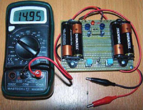
Figure 4 shows an assembled zener-diode-tester circuit. The zener diode under test is On Semiconductor‘s BZX55C15RL, which has a working voltage of 13.8 to 15.6 V. The voltage in Figure 4 was measured at a zener-diode current of 2.8 mA.
 |
|
| Figure 4. | Measure the voltage across a zener diode with a digital multimeter. |
You can use the circuits in figures 2 and 3 to test LEDs, regardless of their color. Place the forward-biased LED you would like to test and set S2 to the lower position. The voltage drop across the 1-kΩ resistor corresponds to the current in milliamps that flows through the LED under test. The circuit can light up even HB (high-brightness) LEDs because, due to their high efficacy, they start lighting at current values as low as a few milliamps.