Requirements for portable, short-range telemetry systems frequently include low power consumption, small size, and low cost. The circuit in Figure 1 meets these criteria and uses only three off-the-shelf ICs and a few passive components. Although dedicated to conditioning the low-level signal a strain-gauge bridge produces, the circuit can operate with almost any resistive transducer based on a Wheatstone bridge. The circuit comprises a VFC (voltage-to-frequency converter) that produces a PPM (pulse-position-modulation) output, and an OOK (on/off-keyed) RF transmitter. Based on direct digitization, the VFC in Figure 1 comprises IC1, IC2, IC3A, and IC3B. A Wheatstone bridge containing strain gauge RX produces an output of approximately 5 mV. An integrator stage comprising C6 and IC1, a LTC1250 offset-compensated, low-drift operational amplifier, connects directly across the bridge. (Note that the value of the remaining resistors in the bridge depends on the application.)
 |
|
| Figure 1. | These RF-telemetry transmitter and strain-gauge amplifier use only three ICs. |
To yield a ratiometric conversion, the voltage applied to the bridge, VCOMP, varies with power-supply voltage and equals the difference between the two threshold voltages of a Schmitt-trigger circuit. In Figure 1, the Schmitt trigger comprises a MAX9075 comparator, IC2; a CMOS inverter, IC3A; and the positive feedback network comprising R1, R2, and C1. Equations 1 and 2 define the Schmitt trigger's high, VTH, and low, VTL, threshold voltages:
 |
(1) |
 |
(2) |
To understand the circuit's operation, assume that the comparator's output is high and, consequently, the inverter's output is low. Also assume that the series combination of the strain gauge, RX, and the trimmer, RT, is always equivalent to R(1 + X) > R. That is, for linear operation, the sensor's resistance variation represents a small fraction of the arm resistance.
Under these conditions, the noninverting input of IC1 biases to VDD/2, and the Wheatstone bridge's active arm drives a positive current, II, into the summing node of IC1. This current causes the integrator's output, VOI, to ramp down toward the low threshold voltage, VTL, of the Schmitt trigger.
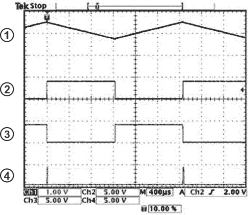
When VOI = VTL, the comparator's output goes to zero, and the inverter's output consequently rises to VDD. This action inverts the direction of the integrator's input current, causing the integrator's output to ramp upward to the Schmitt trigger's high threshold voltage. Finally, when VOI = VTH, the comparator's output goes high, and the above sequence repeats indefinitely, producing a free-running oscillation in which the integrator's output ramps up and down between the threshold voltages of the Schmitt trigger (Trace 1 in Figure 2). Meanwhile, the comparator's output and the inverter's output deliver two square waves with a 50%-duty-cycle ratio (traces 2 and 3, respectively, in Figure 2) that drive the bridge.
To produce the PPM signal (Trace 4 in Figure 2), the inverter's output drives a monostable circuit comprising a second inverter, IC3B, and timing components R4 and C2, which produces a 15-µsec-wide pulse. Current-limiting resistor R3 prevents latch-up of IC3, and R2 and C4 set the output-pulse width.
To model the VFC's transfer function, calculate period TX of the comparator's output. Due to the symmetry of IC1’s output, this period is twice the time the integrator's output takes to ramp linearly between the two threshold voltages of the Schmitt trigger.
Consequently, you can express TX as in Equation 3:
 |
(3) |
where dVOI/dt is the slope of the ramp at the integrator's output. Assuming that the integrator's input current is constant during one period, Equation 4 gives the slope:
 |
(4) |
After applying a Thevenin transformation of the bridge's active arm, you can express the integrator's input current as
 |
(5) |
Replacing VTL, VTH, and dVOI/dt in Equation 3 with the respective expressions from equations 1, 2, and 4 finally yields the frequency in Equation 6.
 |
(6) |
Knowing that X<<1, you can approximate the PPM's output frequency by Equation 7:
 |
(7) |
This transfer function highlights the VFC's three most important features: that the modulation frequency, FX, is directly proportional to the relative variation of the bridge's sensor resistance, RX; that the modulation frequency is independent of the power-supply, VDD; and, therefore, that this PPM converter is ratiometric. This feature is attractive for any portable-system application in which the supply voltage decreases as the battery ages. The modulation frequency is independent of the PPM pulse width, which eliminates the source of error you typically encounter with single-slope VFCs.
Using the components values shown in Figure 1, the converter's frequency span is:
200 Hz < FX < 600 Hz
for a relative variation of the strain-gauge resistance:

Consequently, with zero force applied to the strain gauge, ΔR/R = 0, and the converter produces a 400-Hz modulation frequency. The waveforms in Figure 2 correspond to this case.
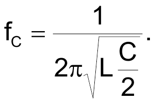
To transmit data over a distance of a few meters, the PPM signal modulates an 80-MHz OOK RF transmitter. This transmitter comprises an interruptible Colpitts oscillator based on a very-high-speed CMOS NOR gate, IC3C; a 74VHC02; and a tank circuit comprising two identical feedback capacitors, C3 and C4; and a square-spiral pc inductor, L1. To obtain reliable oscillation start-up, set C3 = C4 = C. Neglecting the effects of stray capacitances, you can calculate the output frequency of the Colpitts oscillator via Equation 8:
 |
(8) |
The values of L1, C3, and C4 shown in Figure 1 produce a carrier frequency, fC, of approximately 80 MHz. Inductor L1 also doubles as the transmitter's antenna, and its characteristics of eight turns in an 8 × 8-mm pc-board footprint stem from a process that ensures that the transmitter's radiated power never exceeds 250 nW at 80 MHz.
According to European Telecommunication Standard I-ETS 300 220, the transmitter requires no license and can operate at any carrier frequency within the 74- to 87.5-MHz band. Consult applicable regulations for unlicensed transmitter operation in your locality.
At a transmitted power of less than 250 nW, an AM receiver with a tangential sensitivity of 1 µV provides a reception range as long as 10 m, which is sufficient for many indoor-telemetry applications. At a maximum PPM frequency of 600 Hz, the current drain of the circuit in Figure 1 is approximately 2 mA at a supply voltage of 4 V.
References
- Williams, Jim, “Circuits allow direct digitization of low-level transducer outputs,” EDN, Nov 29, 1984, pg 183.
- Williams, Jim, “Digitize transducer outputs directly at the source,” EDN, Jan 10, 1985, pg 201.
