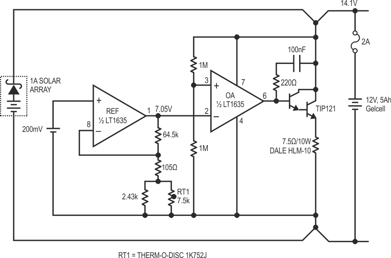
Most battery chargers comprise nothing more than a series-pass regulator with current limit. In solar-powered systems, you can’t count on sufficient headroom to keep a series regulator alive, so a shunt method is preferred. A simple shunt battery charger is shown in Figure 1. It consists of an op amp driving a shunt transistor and ballast resistor, and is built around an LT1635. This device contains both an op amp and a reference, making it perfectly suited for regulator and charger applications.
 |
|
| Figure 1. | 1 A Shunt Battery Charger (IDARK = 230 µA; VFLOAT = 14.1 V). |
Operation is straightforward: the battery voltage is sensed by a feedback divider composed of two 1M resistors. The internal 200 mV reference is amplified to 7.05 V and compared against the feedback. RT1 introduces a TC that accurately tracks the battery’s correct charging voltage over a wide temperature range. Because RT1 is designed to compensate for changes in battery temperature, it should be located close to the battery and as far as possible from the shunt elements. When the battery charges to 14.1 V, the op amp output voltage begins to rise, turning on the Darlington shunt and resisting further increases in voltage. Full panel power is divided equally between the transistor and 7.5 Ω resistor when the battery is completely charged. Don’t forget to provide adequate heat sinking and air flow for up to 15 W dissipation.
The charger is designed to handle 1 continuous, which is compatible with a “20W” panel. There is no need to disconnect or diode isolate the charger during periods of darkness, because the standby current is only 230 µA – less than 10% of the self discharge of even a small battery.
If a different or adjustable output is desired, the feedback ratio can be easily modified at the 1M divider. 14.1 V is a compromise between an aggressive charge voltage and a conservative float voltage. Given the cyclic nature of insolation, allowing periodic charging at 14.1 V is not detrimental to Gelcell batteries. The circuit in Figure 1 will work with larger or smaller batteries than that shown. As a rule of thumb, the panel should be sized from 1 W per 10 A·h battery capacity (a float charge under good conditions with a good battery) to 5 W per 1 A·h battery capacity (1 day recharge of a completely discharged battery under favorable conditions of insolation).