Those of you who imagine that a robot voice generator box would require a whole heap of ICs are mistaken; the ISD2500 ChipCorder family of ICs from Winbond contains almost all the necessary hardware in a single IC to record and playback audio messages. Included on the IC is a microphone preamp and AGC suitable for a low-cost electret type microphone, an output amplifier to drive a loudspeaker, memory, an oscillator, an A/D and a D/A converter.
There are four basic models; 2560, 2575, 2590 and 25120, the numbers following 25 indicate the available recording time in seconds. The memory capacity of each version is actually the same but longer recording times are achieved by using a lower sampling rate. The chip with the shortest recording time therefore offers the best audio quality.
Recordings are made by following this sequence:
First switch S3 to record mode (a low on pin 27). A press of S2 now begins the recording which is ended by another press on S2; a third press of S2 starts the next recoding period and so on. This can continue until there is nothing more to record or when LED D2 lights to show that the memory is full.
Playbacks are made by following this sequence:
Playback can be performed by momentarily toggling S1 and switching S3 into ‘play’ mode, now with each press of S2 the recorded messages will be sequentially played back. The recordings can be overwritten by toggling S1, switching S3 to record and then using S2 to start recording from the beginning again.
Robot voice circuit circuit diagram
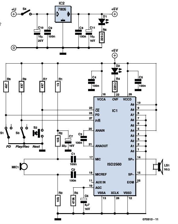
Some flexibility in the playback mode allows individual messages to be linked together; each recorded message is terminated by an EOM (End Of Message) flag when it is stored in the chip. Instead of storing complete phrases like ‘obstacle ahead’ for example it is more efficient to store ‘obstacle’ then ‘ahead’, ‘to the right’, ‘to the left’ and ‘behind’ and likewise for numbers ‘one’, ‘two’, ‘hundred’ ‘point’ etc allows voicing of the complete range of numbers from these basic elements.
The minimum playback circuit shown in uses the A0, PD, /CE and /EOM signals interfaced to the robot microcontroller. For playback PD is reset to ‘0’ and to play the first message a low pulse is given on /CE. With A0 at ‘0’ playback occurs at normal speed but with A0 at ‘1’ the chip enters ‘fast forward’ mode where it advances through the message at 800 times its normal playback speed. When the third message needs to follow the first for example, the processor sets A0 to ‘1’ and pulses /CE low to fast-forward through the second message, waiting for the /EOM flag to go low. Once this occurs A0 is reset to ‘0’ and a low pulse on /CE plays back the third message.
The /EOM output pulse can be less than 10 ms wide so it is better to use it to interrupt the processor rather than just poll its status.