Andy Collinson
Description
In this circuit an electricity supply (domestic or industrial) is continually monitored. Should the supply be interrupted then an alarm will sound for the duration of the interruption. It has battery backup and overcharge protection.
Notes
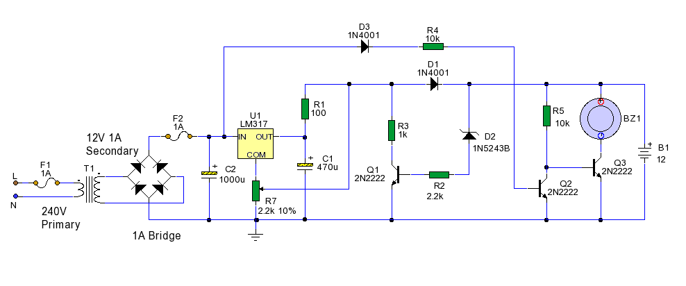
T1 is a transformer that monitors the electric supply. It is rectified by a bridge rectifier and smoothed by C2 giving a 15 Volt DC supply. The 15V supply is the input to the LM317 regulator. The regulator output is set by R1 and R7 to about 12.7 Volts. Battery B1 is a 12 Volt lead acid battery. It can be 3 A-h capacity or higher if required. The battery is trickle charged via D1 and R1, trickle current being several milliamps. Q2, Q3, R5 and BZ1 ( a piezo sounder) form a solid state alarm. As long as the power is on, D3 and R4 positively bias Q2 into saturation. Q2 collector will be close to zero, and hence Q3 and the sounder will be off also.
Should the supply fail, then C1 rapidly discharges, there is no more positive bias for Q2 base and the transistor goes into cut-off. Now Q3 saturates via R5 and the piezo sounder operates. There is no way to stop this alarm so a series switch can be added if desired to disable the sounder.
As long as power is applied battery B1 will continually charge. Should the voltage reach 14 Volts then Zener D2 will avalanche. This then activates Q1 and the input voltage at R7 wiper will be reduced and the charging supply for the battery will be cut off. Battery B1 will then continually monitor Q2, Q3 and the sounder.