LEDs need current to illuminate, and current usually flows through a power supply to an LED. A typical LED-driver circuit uses a transistor to provide current and a series resistor to decrease the voltage you apply to the LED. Unfortunately, the energy (VSOURCE – VDIODE) × IDIODE in a transistor/resistor combination goes to waste, giving off heat.
 |
|
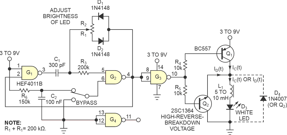
| Figure 1 | This circuit lights an LED without wasting power when the source voltage is much higher than the LED’s operating voltage. |
The circuit in Figure 1 can minimize this waste by using an inductor and an oscillating circuit to control the current through the LED – energy that would otherwise go to waste. Inductor L1 stores power and channels it back into the LED.
You might think to put two or more LEDs in series instead, but that configuration doesn’t let you change the intensity and still save power. This circuit provides a general way of saving power without worrying about the intensity issues or operating voltage of the device. Transistors Q1 and Q2 alternately turn on and off. Q1 increases the current through the LED from a certain minimum value when it connects the L1/LED combination to a voltage source. Transistor Q2 discharges stored energy in inductor L1 through the LED. The current falls between a maximum and a minimum. Assume that transistors Q1 and Q2 are lossless switches in the analysis of this circuit.
Because the inductor doesn’t let the current grow suddenly, it controls the average current through the LED to a desired value. The inductor also stores energy, which also powers the LED. The following equations, which apply to the output of G2, set the on- and off-times:
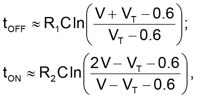
where V is the supply voltage and VT is the input threshold voltage of the CMOS gates at supply-voltage V.
You can expect efficiencies as high as 80% with this circuit.
In this circuit, the supply current is less than the current through the LED because of the stored energy.
The current through the LED has a maximum and a minimum, which the on- and off-times of Q1 and Q2 set, along with other parameters, such as the value of L1. You can use a 5- to10-mH ferrite-core inductor for L1 with a white LED with a forward-voltage drop of approximately 3 V. For supply voltages of 7 to 15 V, use a better transistor than Q2, such as the 2SC3134, because of the reverse breakdown voltage of the base-emitter junction. The 2SC1364 transistor in the figure works well at voltages as high as 9 V. The equations apply to the CD4011B, although you can substitute the HEF4011B, which consumes less power.