Conventional astable oscillator circuits that use CMOS logic gates, bipolar transistors or low current op Amps, often require more current than necessary. The circuit shown generates a low frequency square wave signal while drawing only 0.5 microamps from a 6 volt supply. The circuit uses a number of N and P channel MOSFETs, contained within an inexpensive CD4007UB IC. The circuit is inspired by a classic bipolar emitter coupled oscillator design and works in much the same way.
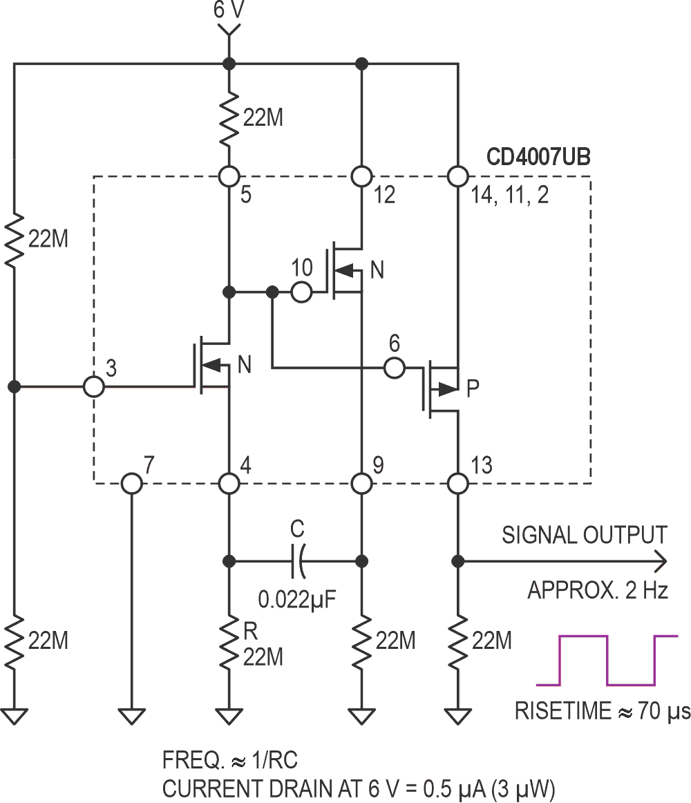
The first N channel transistor is biased to the mid-supply point. The gate of a second N channel device is connected to the drain of the first, which provides a 180 degree phase shift. An additional 180 degree phase shift is created by cross linking the transistor's two source terminals through a capacitor. The positive feedback that results, causes current to slosh back and forth through the common source coupled capacitor and forces the circuit to quickly break into oscillation. The signal produced at the drain of the first transistor is buffered by a third P-channel transistor. With the components shown, the output frequency is about 2 Hz. The frequency is approximately equal to 1/RC. With a careful circuit layout, the frequency can be pushed to about 300 Hz with a 68 pF timing capacitor. If higher frequencies are desired, the value of the load resistors would have to be decreased. Although the output signal has a 70 µS rise time, it would still require some kind of Schmitt trigger buffer if it is expected to toggle a counter or a flip/flop IC.