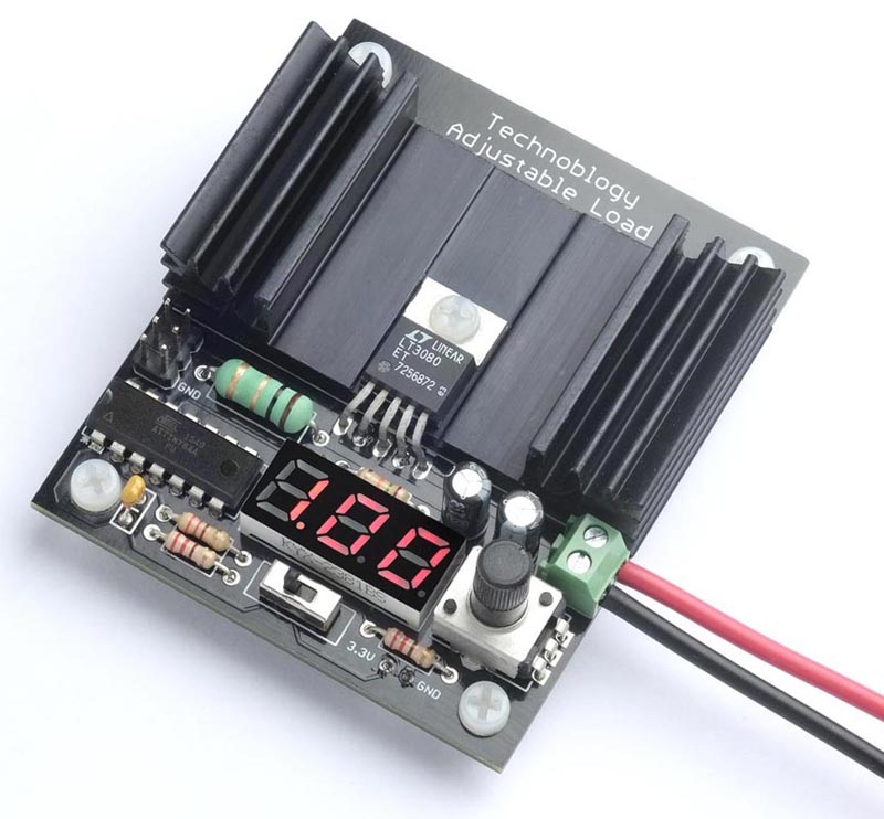
An adjustable load in Figure 1 provides a constant-current load for testing power supplies and batteries. It allows you to set the load current to up to 1.05 A, using a potentiometer, and displays the current on a three-digit LED display controlled by an ATtiny84.
 |
|
| Figure 1. | The Adjustable Load, based on an LT3080 regulator and an ATtiny84A processor, drawing 1 A from a power supply being tested. |
As well as testing power supplies, the adjustable load can be used for testing rechargeable NiMH and Li-ion batteries under different load conditions. It measures the current over time, and displays the battery's capacity in mA·h or A·h. This is useful for comparing different makes of battery, or for deciding whether a battery has reached the end of its life.
Introduction
To test a power supply you typically want to run it into a load, to see how it handles at the limit of its current handling capability, check its heat dissipation, and measure the noise and ripple on the output. One way is to use a high wattage resistor, but this only lets you check one fixed load. The solution is an adjustable load; a circuit that simulates a load and lets you adjust the current through the load over a wide range.
I recently needed an adjustable load for two different projects I was working on. I wanted to check my Power Deliverer with Current Monitor [1] at different voltages and currents, and I also wanted to check the capacity of several lithium rechargeable batteries to determine whether they actually matched their published mA·h rating.
I had already built an adjustable load in an earlier project, Adjustable Load [2], but unfortunately I had dismantled the prototype, so I decided to design a PCB for a new circuit. Initially I thought of updating the design to use an OLED display, rather than the original LED display, and a new 0-series ATtiny processor rather than the ATtiny84 used in the original, but I decided there were advantages in keeping to the original circuit. It's a proven circuit, so I could go straight to designing a PCB, and all the components are through-hole, so you don't need SMD skills to build it. I've made a few improvements to the circuit and program, but it's essentially the same as the original.
The circuit
The full circuit of the adjustable load is shown in Figure 2.
 |
|
| Figure 2. | Circuit of the adjustable load, based on an LT3080 regulator and ATtiny84 processor. |
The constant-current circuit is based on an LT3080 regulator. This uses a current reference of 10 µA, rather than a voltage reference like regulators such as the LM317, and will operate down to 1.5 V and a few mA.
The current is sensed by a 1 Ω resistor, and this is fed to the sense input of the regulator, via a 100 kΩ potentiometer and 5.1 kΩ resistor. Since the current through the potentiometer and resistor is 10 µA, at the potentiometer's maximum setting the voltage across them will be 1.05 V, so the output of the regulator will be maintained at 1.05 V across the 1 Ω resistor, producing a constant current of 1.05 A.
The LT3080 is available in a few different packages. I chose the TO-220-5 package which provides a separate VCON pin, and is convenient to mount on a heatsink.
The current is displayed on a three-digit 7-segment display. I used a 0.28" three-digit common anode seven-segment LED display.
You could power the ATtiny84 and display from the power supply you are testing, via a 3.3 V regulator. However, I decided to use a separate 3.7 V Lipo battery because this gives two advantages: First, it allows you to test inputs down to as low as 1 V. Secondly, it ensures that the microcontroller and display remain powered even when the test supply drops to zero, which is essential for battery testing.
The potentiometer is a 100 kΩ linear type. I used an Alps Alpine RK09K1130C94. Another suitable one is the Bourns PTV09A-4020U-B104. I added the 5.1 kΩ series resistor because I wanted to be able to adjust the current slightly above 1 A.
For the LT3080 to regulate, the VCON voltage must be more than 1.2 V to 1.35 V greater than the output voltage. In some applications this pin can simply be connected to VIN, but here this would limit the minimum voltage that the adjustable load can control to about 2 V. The solution is to connect it to the 3.7 V supply used to power the ATtiny84 and display.
Construction
I designed a PCB in Eagle and ordered boards from PCBWay. I designed the PCB to fit the heatsink I used. This has a thermal rating of 6.8 °C/W. With a current of 1 A at 5 V the voltage across the LT3080 will be 4 V, so the power will be 4 W; the heatsink will therefore be 27.2 °C above the ambient temperature, or typically 47.2 °C. This is safely below the LT3080's recommended maximum operating temperature of 90 °C.
I've provided a 2.35" × 1.25" area of copper on the PCB which you could use as a heatsink. There's a rule of thumb that says that "one Watt of power dissipated in one square inch of two-ounce copper generates a 100 °C temperature rise" [3] so this will only provide a thermal rating of about 34 °C/W and won't be sufficient if you want to run the Adjustable Load at its full current.
The TO-220 LT3080 is designed for vertical mounting so you need to gently bend the leads with a pair of flat-nose pliers to fit the PCB. Attach the regulator to the heat sink and board with an M3 screw and nut.
All the components are through-hole, so it should be easy to solder by hand. Mount the 1 Ω/2 W resistor slightly above the board to improve airflow around it.
The PCB includes space for a 2×3 pin ICSP connector that you can use to program the ATtiny84A. For details see Compiling the program below.
The total current consumption of the controller is about 10 mA; I power it from a small 3.7 V Lipo cell connected to the two terminals and attached to the bottom of the board with a double-sided foam sticky pad. You could alternatively use a pair of 1.5 V AAA batteries in a battery box.
The program
Displaying the current
The voltage across the 1 Ω resistor is read by an analogue input on an ATtiny84, and this then displays it on a three-digit seven-segment display. The analogue input, ADC7 on PA7, is configured by SetupADC() to use the 1.1 V reference voltage:
void SetupADC () {
// Set up ADC on ADC7 (PA7)
ADMUX = 2‹‹REFS0 | 7‹‹MUX0; // 1.1V ref, ADC7 (PA7)
ADCSRA = 1‹‹ADEN | 4‹‹ADPS0; // Enable ADC, 62.5kHz clock
}
The analogue value is read by the routine ReadADC ():
int ReadADC () {
unsigned char low, high;
ADCSRA = ADCSRA | 1‹‹ADSC; // Start
while (ADCSRA & 1‹‹ADSC); // Wait while conversion in progress
return ADC;
}
I used a common-anode seven-segment LED display, but you could use a common cathode display by changing a few lines in the DisplayNextDigit() routine.
Timer/Counter0 multiplexes the display, and this is configured by SetupTimer0() to generate an interrupt at 312.5 Hz, which is fast enough to avoid flicker:
void SetupTimer0 () {
TCCR0A = 2‹‹WGM00; // CTC mode
TCCR0B = 0‹‹WGM02 | 3‹‹CS00; // Divide by 64
OCR0A = 49; // Divide by 50 for 312.5Hz interrupt
TIMSK0 = 1‹‹OCIE0A; // Enable compare match interrupt
}
The interrupt service routine simply calls DisplayNextDigit():
ISR(TIM0_COMPA_vect) {
DisplayNextDigit();
}
This puts the appropriate segment data onto PORTA for the next digit to be displayed, and then takes the digit common line high on PORTB. The number to be displayed on each display digit is specified by the array Buffer[]:
void DisplayNextDigit() {
static int LastReading;
DDRB = 0; // Make all digits inputs
DDRA = 0; // Make all segments inputs
digit = (digit+1) % (Ndigits+1);
if (digit < Ndigits) {
char segs = charArray[Buffer[digit]];
if (digit == DP) {
DDRB = DDRB | 0x04; // Decimal point output
PORTB = PORTB & 0xFB; // Decimal point low
}
DDRA = segs & 0x7F; // Segments outputs
PORTA = ~segs & 0x7F; // Segments low
DDRB = DDRB | 1‹‹Digits[digit]; // Make digit an output
PORTB = PORTB | 1‹‹Digits[digit]; // Take digit bit high
} else {
// Read analogue input
Current = (ReadADC()*29)/27;
// If current near zero, display charge
if (Current < 100) { // < 0.1A
int mAh = Charge/3600;
if (mAh < 1000) Display(mAh, -1); else Display(mAh/10, 0);
LastReading = 0;
} else {
// Add hysteresis to stop display jumping
if (abs(LastReading - Current) >= 10) {
Display((Current + 5)/10, 0);
LastReading = Current;
}
}
}
}
Every fourth cycle this routine blanks the display, to minimise interference with the analogue input, and then calls ReadADC() to read the voltage across the 1 Ω resistor. Since the ADC is using a 1.1 V reference, a reading of 1024 corresponds to 1.1 V, so the current in mA is 1100/1024 times the reading. 29/27 is a good approximation to this, and avoids long arithmetic. See Calibration below for details of how to fine-tune this.
The routine then calls Display() to display the current in amps or, if the current is zero, the charge in A·h or mA·h. The routine Display() simply writes the three digits of the value into the array Buffer[].
Calculating battery capacity
The battery capacity feature uses Timer/Counter1 to generate a 1 Hz interrupt; this is configured by SetupTimer1():
void SetupTimer1 () {
TCCR1A = 0‹‹WGM10;
TCCR1B = 1‹‹WGM12 | 3‹‹CS10; // Divide by 64
OCR1A = 15624; // Divide by 15625 for 1Hz interrupt
TIMSK1 = 1‹‹OCIE1A; // Enable compare match interrupt
}
The interrupt service routine sums the current every second to calculate the total charge. It also flashes the decimal point to show that the circuit is operating:
ISR(TIM1_COMPA_vect) {
Charge = Charge + Current;
if (Current != 0) DP = DP ^ 0xFF; // Flash decimal point
}
Applications
Testing a power supply
The adjustable load allows you to test a power supply you have built, or a commercial power supply, to see how it handles different loads, check its heat dissipation, and measure the noise and ripple on its output.
Connect the power supply to the adjustable load, observing polarity, and adjust the potentiometer to the load you want to simulate.
Checking rechargeable battery capacity
To test the capacity of a rechargeable battery, charge it fully, and then connect the battery to the adjustable load, observing polarity. Adjust the current to the maximum value that the battery can handle.
Unless otherwise specified, most Li-ion batteries have a maximum discharge rate of 2C, which means that the maximum current is twice their rating in mA·h; for example, a 350 mA·h battery has a maximum safe discharge rate of 700 mA. This has the interesting consequence that at their maximum discharge rate every battery should last half an hour.
When the current drops to zero, either because the battery is exhausted, or because you have disconnected the battery, the meter automatically switches to displaying capacity rather than current. For capacities of up to 999 mA·h the display shows the number of mA·h; otherwise it shows the number of A·h, up to 9.99 A·h. To reset the capacity measure switch the power off and on again.
I used the Adjustable Load to compare two 3.7 V lithium 10440 batteries. These are convenient cells to use for projects because they fit in a standard AAA battery holder. One was a PKCELL battery rated at 350 mA·h, and the other was a TrustFire battery rated at 600 mA·h. It seemed a bit implausible that the second manufacturer managed to squeeze nearly twice the capacity from the same size of cell.
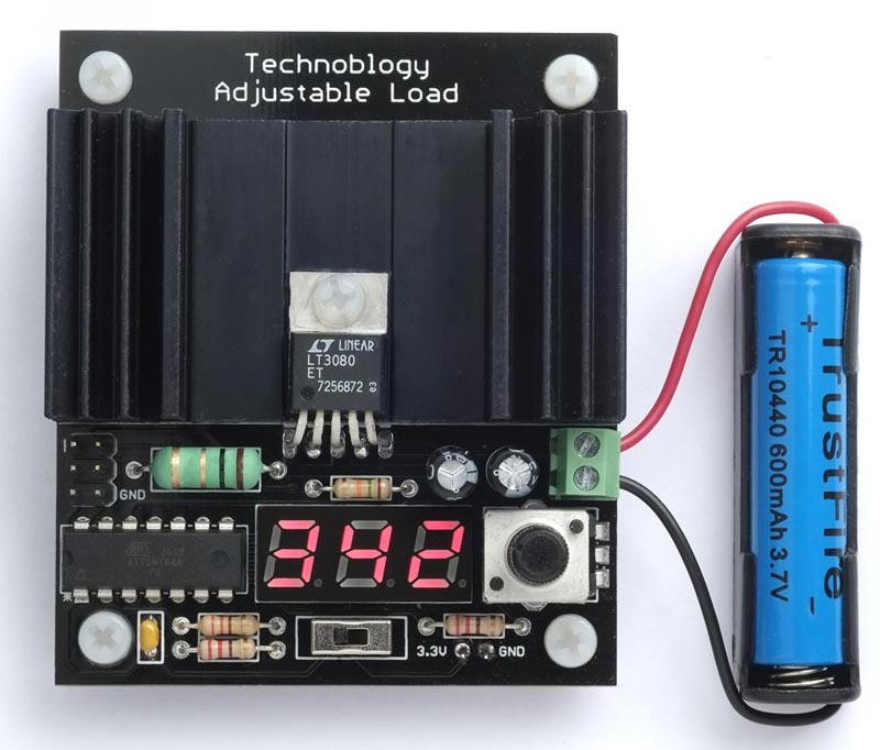
For each cell, after fully recharging it, I connected it to the Adjustable Load with the current set to 0.70 A. After about half an hour each cell had stopped producing a current through the load, and the displays switched to showing the capacity (Figure 3).
 |
|
| Figure 3. | Using the adjustable load to measure the capacity of a rechargeable battery. |
The PKCELL showed a capacity of 334 mA·h, which is close to the rated capacity, but the TrustFire battery showed a capacity of 342 mA·h, which was what you might expect from its size, but well below its advertised capacity of 600 mA·h.
Calibration
There are a couple of calibrations you can make to improve the accuracy of the adjustable load.
Current
The LT3080 datasheet gives the accuracy of the 10 µA reference current as ±1%, but the main source of inaccuracy is probably the 1 Ω load resistor. Fortunately it's easy to correct for this by adjusting the ratio 29/27 in the line of the program:
Current = (ReadADC()*29)/27;
Connect a power supply to the Adjustable Load through a digital multimeter capable of measuring 1 A, and set the Adjustable Load current to read 1.00 A. Then, scale the factor 29/27 by d/1000, where d is the digital multimeter reading in mA.
Battery capacity
The battery capacity calculation relies on the internal oscillator for timing, which is accurate to about 10%. If you want greater accuracy you can calibrate it using the OSCCAL register to within about 1%. Measure the frequency on PB1 (the left-hand lead of R2, the 220 Ω resistor nearest the front of the board) with the frequency range of a multimeter, and recompile the program with different values of OSCCAL until the frequency is as close as possible to 78.125 Hz.
Compiling the program
Compile the program using Spence Konde's ATTiny Core [4] on GitHub (I used 1.5.2). Choose the ATtiny24/44/84(a) (No bootloader) option under the ATTinyCore heading on the Board menu. Check that the subsequent options are set as follows:
Chip: "ATtiny84(a)"Clock: "1 MHz internal"
This is the default fuse setting on new ATtiny84s; otherwise choose Burn Bootloader to set the fuses appropriately. Then upload the program to the ATtiny84 using a suitable ISP programmer such as the Tiny AVR Programmer Board; see ATtiny-Based Beginner's Kit [5].
Note that while the ISP programmer is connected to the circuit the MOSI connection may cause the A segments of the displays to light up, so to avoid misleading displays when testing the board disconnect the programmer.
References
- Johnson-Davies, David. "Power deliverer with current monitor."
- Johnson-Davies, David. "Adjustable load."
- Accurate Thermal Calculations on the Back of a Napkin
- megaTinyCore
- ATtiny-Based Beginner's Kit