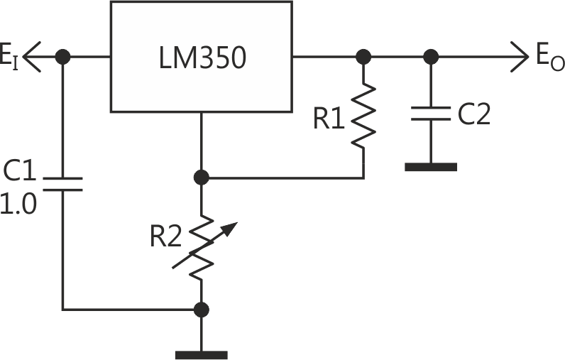
Figure 1 shows a typical using of LM350 (LM317) adjustable regulator when you need to adjust its output voltage.
 |
|
| Figure 1. |
This voltage is approximately given here as:
The potentiometer R2 is often the most unreliable part of the circuit. As shown in the expression above, a breakdown of the potentiometer (e.g., loss of contact, open circuit) maximizes the effective value of R2, making the output voltage maximal also – about only 1.5 V lower than the input voltage.
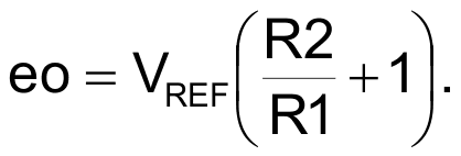
This may be not a very big problem when the adjustments are rare, and the safety of the load has no critical importance. But, when you want to make frequent adjustments, or the load is not known beforehand – like in the case of a laboratory power supply – the circuit in Figure 2a may be far better choice.
 |
|
| Figure 2a. |
However, this circuit cannot regulate its output voltage down to the low limit VREF; this is its limitation.
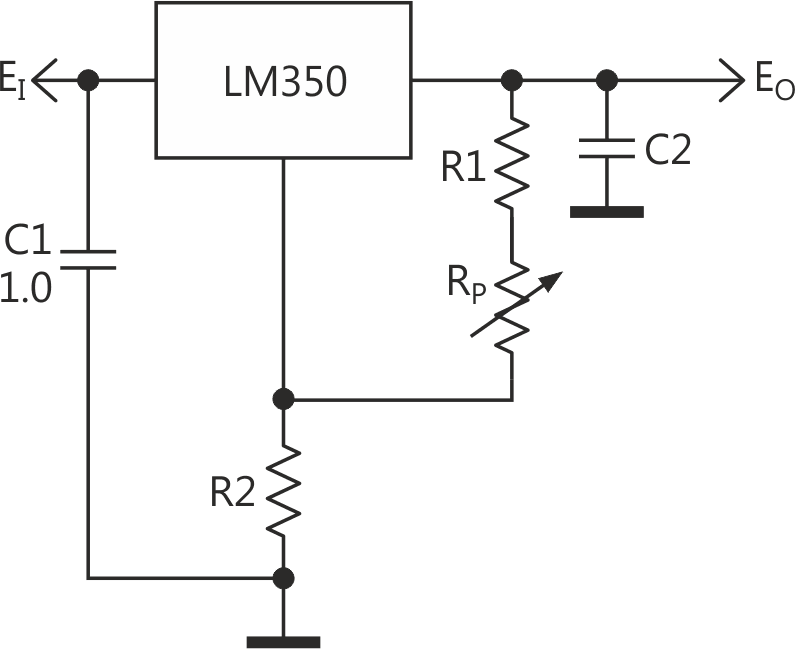
There are several alternative configurations of safe adjustable regulators that more or less avoid the danger of the overreach. The safest case, where output voltage drops very close to VREF, would demand 3 or 4 extra parts (i.e., resistors and transistors); so, let’s look at a configuration with more compromise in Figure 2b.
 |
|
| Figure 2b. |
This circuit can regulate its output voltage down to the low limit VREF. The output voltage (if a breakdown of potentiometer RP occurs) is about 2…5 volt, which is a compromise.
Since a calculation of the circuit in Figure 2b is not very straightforward, the calculation of the resistors R22 and R23 will be provided here as a Python code (see Downloads section).
The circuit has two ranges of the output voltages: from eo11 to eo12, and from eo21 to eo22 (see code). The range is selected by a switch Sw (e.g., nJFET, nFET, or any good mechanical, reed relay).
Please note: if the resistors R11 and RP are too large to provide the minimal load needed by the regulator IC (up to 10 mA max), the output may rise out of control if the total load is too light.
To avoid this, it may be wiser to begin a calculation choosing any appropriate value for R11.
You have to provide the values of RP and range(s) as well.
The 50 μA (typ.) current IA from the adjustment terminal, representing an error term, makes a voltage drop on R23. Together with a nominal 1.25 V reference voltage, VREF, this drop determines the output voltage when a breakdown of potentiometer RP occurs:

So, when decreasing the value of R22 you can decrease – to some extent – the value of eoBreak.