DIY Laser Scanning Microscope made from a defective Blu-Ray Player.
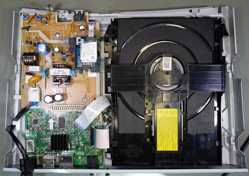
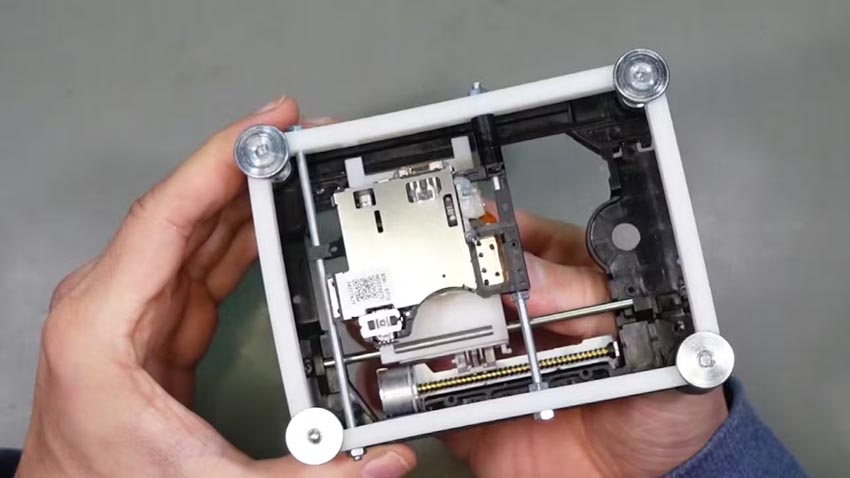
A Blu-ray player must be able to detect the microscopically tiny pits on DVDs in order to play back a film. Therefore, the question arises: Can a Blu-ray player also "see" other structures? This would mean that we can turn it into a microscope or at least use its parts to construct one. To do so, we first need to open a blu-ray player to find out how the detection system works (Figure 1).
 |
|
| Figure 1. | Guts of a Samsung BD-J5900 Blu-ray player. |
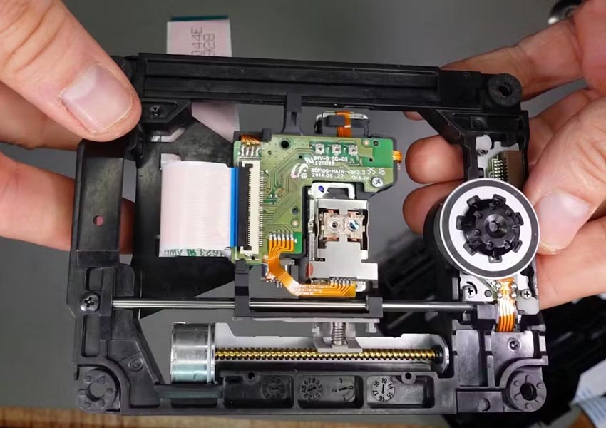
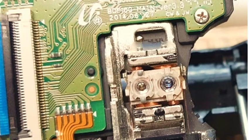
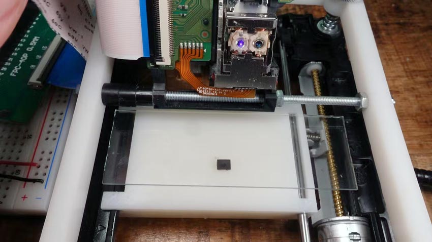
The heart piece is the optical pickup unit, OPU for short. This is dragged across the laser disc by a small stepper motor with spindle. In Figure 2, you can also see the BLDC motor that spins the disc.
 |
|
| Figure 2. | OPU on its carriage. |
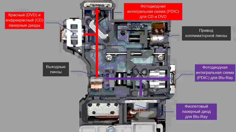
An OPU contains a laser diode which emits violet light with 405 nm wavelength to read Blu-ray disks, a "red" laser diode with 650 nm to read DVDs and an "infrared" laser diode with 780 nm for the CDs (Figure 3). The light gets focussed and directed to the disk by lenses and mirrors, where it gets reflected and led to an array of photo diodes, the Photo Diode Integrated Circuit (PDIC).
 |
|
| Figure 3. | Optical Pickup Unit (OPU). |
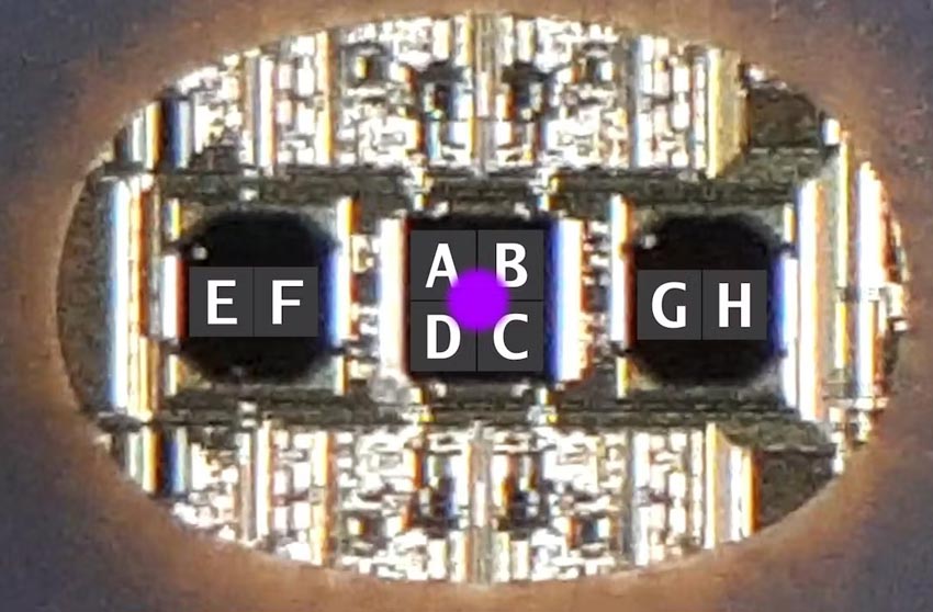
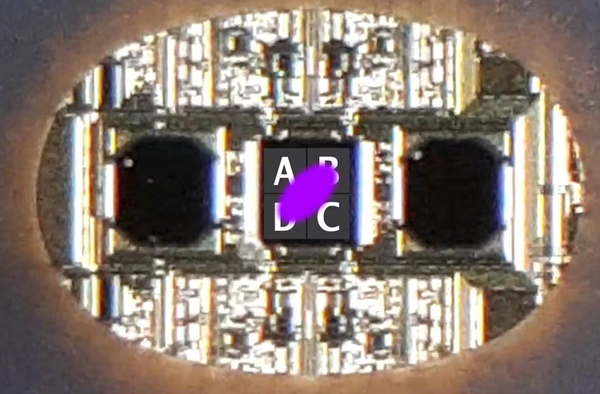
As you can see In Figure 4, a PDIC consists of three areas. The field in the middle has four light sensitive areas named from A to D. Their outputs are used to measure the amount of reflected light and the distance between the lens and the disk in order to focus it. The output of the outer fields E-H helps to keep the laser on its track.
 |
|
| Figure 4. | Photo Diode Integrated Circuit (PDIC). Laser is in focus, FES = 0. |
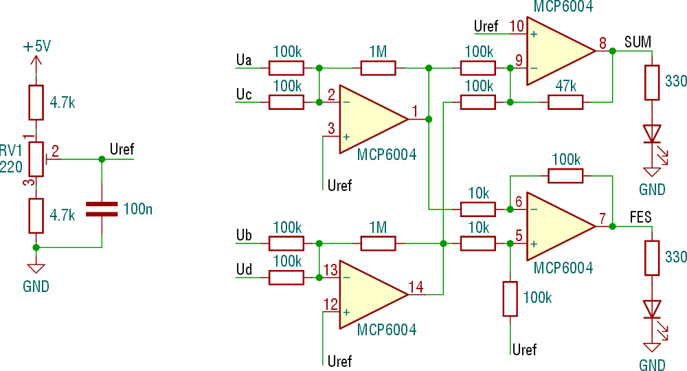
For my scanning microscope, the outputs A-D are used. To get the total amount of the reflected light, we need to add the outputs auf the fields A-D. This returns the sum signal A + B + C + D. If the laser is perfectly focused on the target (usually an optical disc), the reflection on the PDIC is circular and all fields return the same output value. If out of focus, the reflection becomes more or less elliptic with an angle of 45 degrees (Figure 5). So we can calculate the focus error signal:
FES = (A + C) – (B + D).
 |
|
| Figure 5. | Laser out of focus, FES 0. Here: FES < 0. |
Both the sum and die FES can be used to create the image in software. Sum and FES are calculated analogously using the four operational amplifiers of an MCP6004 (Figure 6). These are then fed into two analog inputs of an ESP32.
 |
|
| Figure 6. | Circuit to calculate SUM and FES. |
The lenses of the OPU are surrounded by magnets and coils (Figure 7). These focus the laser beam on its target (usually the disc) and position it so that it stays on its track. On my Blu-ray microscope, these coils perform the scanning of the lines (X-direction). They are also controlled by a PWM signal from the ESP32, which gets amplified by a L293 motor driver IC.
 |
|
| Figure 7. | Laser outlet lenses of an OPU. |
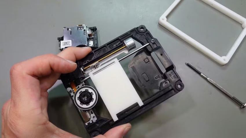
I replaced the OPU by a 3D printed platform on which I can later put the sample I want to magnify (Figure 8). This will be dragged in Y direction by the stepper motor and the spindle. The motor is driven by an A4988 stepper motor driver module.
 |
|
| Figure 8. | 3D printed platform for specimem dragged by spindle. |
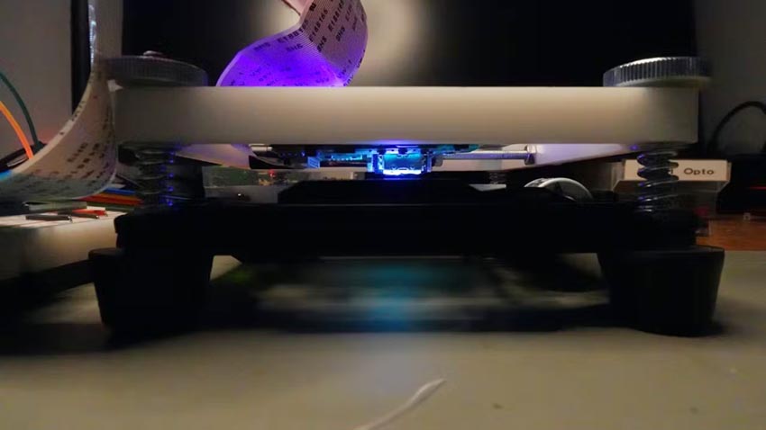
The OPU gets mounted above this arrangement. It sits between two threaded rods and is kept in place by spacers and nuts (Figure 9). It is not supposed to move in any direction.
 |
|
| Figure 9. | Top view of the Blu-ray Microscope. |
However, it can be flipped open for an easy insertion of the specimen (Figure 10).
 |
|
| Figure 10. | Laser Microscope with sample. |
The distance between the OPU's outlet lenses and the sample can roughly be adjusted by knurled nuts (Figure 11). Fine adjustment is done by the focus coil. The focal length is approximately 1 mm.
 |
|
| Figure 11. | Blu-Ray microscope with sample. |
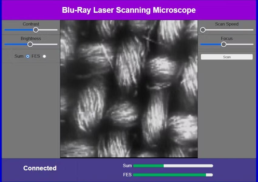
The Blu-ray microscope is controlled by an ESP32. With built-in WLAN, this chip is perfectly suited for all kind of web based applications. So the microscope can be operated through a website using HTML and JavaScript. The picture in Figure 12 shows the HTML controls and a piece of fabric.
 |
|
| Figure 12. | Website of the laser microscope. |
The scanned area is approximately 1 × 1 mm, resolution is currently 127 × 100. This is limited by the precision of the mechanism that drags the sample under the OPU lenses along the Y-direction. Perhaps the use of a finer spindle and a stepper motor driver capable of more microsteps than the A4988 can improve this further. But even with this resolution, we can clearly make out some details, such as the fibers from which the threads of the fabric are spun.
Materials on the topic
- Datasheet Allegro A4988
- Datasheet Texas Instruments L293
- Datasheet STMicroelectronics L7805
- Datasheet Fairchild LM317
- Datasheet Microchip MCP6004
- Datasheet STMicroelectronics BD677