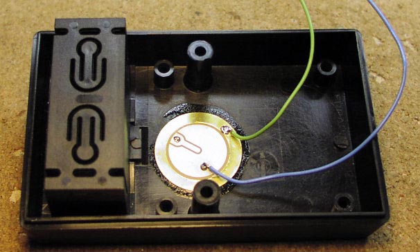
This circuit uses a flat piezoelectric wafer, glued inside a plastic box, as a finger tap sensor. With each tap of a finger to the box holding the wafer, the circuit turns on and off AC or DC power to an external device. The circuit is powered by a 9 V battery and drives a single coil 5 V latching relay with a 10 A contact rating. The relay can switch AC or DC power. In standby mode the circuit draws a low 1 µA.

A firm finger tap to the plastic box cover causes the piezoelectric wafer to produce multiple voltage pulses. The pulses are fed to a low power voltage comparator. The comparator converts the low voltage pulses into 9 V pulses. Those pulses are fed to the clock input of one half of a CD4013 dual D flip/flop. One section is configured as a half second one shot. The second half is wired as a standard flip flop.
With this circuit, the flip/flop changes state with each finger tap to the box, holding the circuit. The output of the flip/flop is connected to a dual FET push-pull driver circuit, which feeds power to a pair of capacitors. The capacitors are wired in series with parallel diodes. This forms a 235 µF non-polarized capacitor. With this charge pump configuration, the power pulses from the FETs feed either a positive pulse to the relay coil, to latch it, or a negative pulse to unlatch it. The pulse lasts long enough to fully open or close the relay contacts.