Are you tired of dealing with the damaging effects of inrush currents on your industrial devices? Look no further than an AC inrush current limiter (soft starter). Inrush current, also known as surge current, is the large amount of current that flows into a load at start-up. This can cause damage to equipment, reduce its lifespan, and lead to costly downtime. But with an AC inrush current limiter, you can eliminate these problems. Simply, a soft starter works by limiting the initial current flow, ensuring a smooth and efficient start-up, while protecting your equipment from damage.
So I decided to design this AC soft starter that is equipped with a fail-safe mechanism. During start-up, the inrush current passes through a power resistor, and after a delay (adjustable between 1 ms to 1 s), a 30 A power Relay shorts the resistor and applies the full power to the load. If this Relay fails for whatever reason, the power resistor won’t melt everything; the logic circuit activates the fail-safe Relay that turns OFF the load to prevent any damage. 3 LEDs indicate the Supply, Normal, and Fault conditions. I selected the cheap ATtiny13 MCU as a controller.
To design the schematic and PCB, I used Altium Designer 23. I used the Arduino IDE to write the MCU code, so it is pretty easy to follow and understand.
Let’s get started.
Circuit analysis
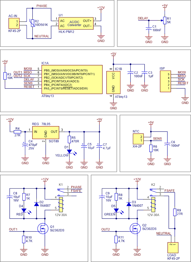
Figure 1 shows the schematic diagram of the device. As it is clear, the heart of the circuit is the ATtiny13 microcontroller.
 |
|
| Figure 1. | Schematic diagram of the 30 A AC Soft Starter (Inrush current limiter). |
I start explaining the schematic from the top. AC-IN is the connector for the AC Mains input. R2 is the 10D5651K varistor to eliminate voltage spikes at the input. U1 is the HLK-PM12 AC to DC module that handles 12 V at the output. This voltage is suitable to drive the Relays. R1 is a 5K potentiometer to adjust the delay. You can adjust the delay to something between 1 ms and 1 s. ISP is a male pin header for the AVR ISP programmer. IC1A and IC1B are parts of the ATtiny13 microcontroller. R3 is a pullup resistor for the RESET pin. C2 and C3 are decoupling capacitors for the VCC pin.
R4 and C4 build an RC filter at the input of the REG1. REG1 is the 78L05 SOT-89 5 V regulator to build a stable 5 V power for the microcontroller. D1 is a 3 mm yellow through-hole LED to indicate a proper supply voltage and R5 limits the current to D1. C5 and C7 are output capacitors to stabilize the regulator output voltage and reduce the noise. NTC is a 2 Pins XH connector to wire a 10K NTC to the board. R6 and NTC build a voltage divider, where voltage variations indicate changes in the temperature. If the temperature increases at the NTC side, the output voltage increases, and vice versa. C6 is a decoupling capacitor to reduce noise.
There are two Relay circuits here, both are identical. I explain one of them. Q1 is a Si2302 MOSFET to drive the K1 Relay. R10 is a pulldown resistor for the Gate pin of Q1 to prevent unwanted triggering of the MOSFET. D2 is a 1N4007 diode to protect the MOSFET against reverse currents of the Relay’s coil. D4 is a 3 mm Red LED to indicate the fault condition. C8 damps the voltage spikes of Relay activation/deactivation. R9 is a 27R-20W power resistor to limit the inrush current, you can use other values depending on your application.
PCB layout
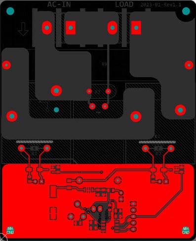
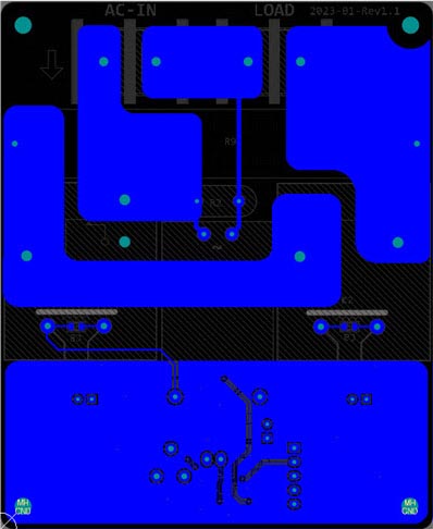
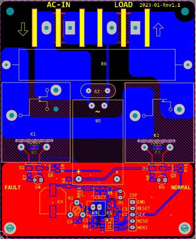
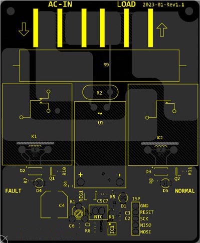
Figure 2 shows the PCB layout of the design. It’s a two layers PCB board and I used a mixture of SMD and through-hole components. In my opinion, component placement is the first rule in a good PCB design. In this PCB, the separation between the power and logic circuits is clear.
|
|||||
| Figure 2. | PCB layout of the 30 A AC Soft Starter (Inrush current limiter). | ||||
Code
I use the Arduino IDE to write and compile the MCU code. I installed the MicroCore [1] in the library manager to be able to compile the code for ATtiny13. I have already provided the compiled HEX file which you can download from the link in the Downloads section. The only thing you need is just connecting your programmer to the ISP header on the PCB board and program the MCU. Fuse bits must be set on the 9.6 MHz internal clock, with no clock division (disable DIV8).
If you plan to modify the program, its source code is available at the link in the Download section.
Assembly and test
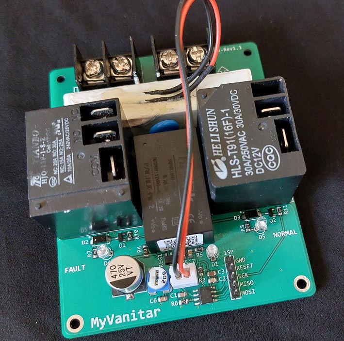
Figure 3 shows the assembled PCB board. You should wire a small 10K NTC from the board and mount it on the power resistor. The best method to fix the NTC is to use some silicon glue (thermal conductive glue). Simply adjust the potentiometer for your desired delay. Pay attention to the status of 3 LEDs (Yellow, Green, and RED).
 |
|
| Figure 3. | Assembled board of the 30 A AC Soft Starter (Inrush current limiter). |
Bill of materials
Table 1 shows the bill of materials for the project.
| Table 1. | Bill of materials for the 30 A AC Soft Starter (Inrush current limiter) project |
|||||||||||||||||||||||||||||||||||||||||||||||||||||||||||||||||||||||||||||||||
|
||||||||||||||||||||||||||||||||||||||||||||||||||||||||||||||||||||||||||||||||||