Version 1
A single lithium ion battery cell needs 4.2 V from a current source to insure it is fully charged. A solar panel with just enough individual cells wired in series to produce the needed voltage would be more efficient than one with more cells for a given surface area. If you divide 4.2 by eight you come up with a figure of 0.525 volts.
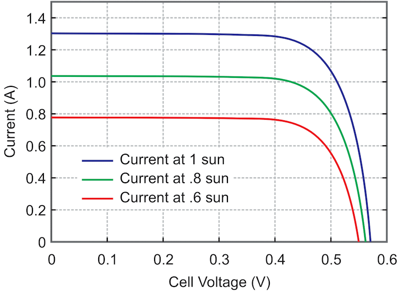
That means if an 8 cell solar panel were used, each cell would need to produce 0.525 volts to insure it could charge a lithium ion battery. As the curve in Figure 1 indicates, a typical solar cell does indeed produce such a voltage and could be used to charge the battery but only if the charge circuit had a very low voltage drop to maintain the 4.2 V.
 |
|
| Figure 1. | Basic PV cell behavior. |
Note that at one full standard sun intensity, only about 70% of the peak current is available at the needed 0.525 volt point. However, as a lithium ion battery reaches the target 4.2 volts, the charge current naturally tapers off, so this reduction in current may not translate into much of a reduction in overall efficiency.
 |
|
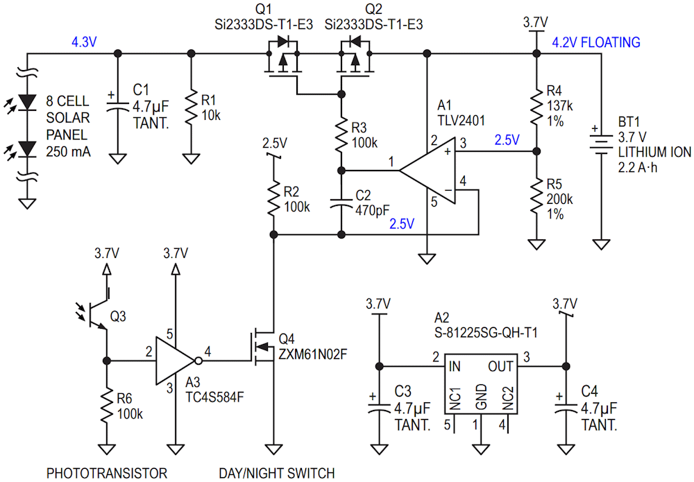
| Figure 2. | Schematic diagram of the charger. Version 1. |
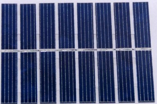
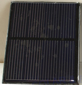
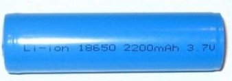
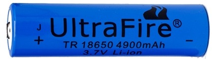
An ideal charger circuit would limit the charging battery voltage to 4.2 V but also have a very low voltage drop, when delivering current to the battery. Also, during night time, when the solar panel is not producing any current, the circuit would need to block current from flowing back into the solar panel from the battery. These two needs often conflict with each other. The circuit in Figure 2 supplies both needs. A photodiode is used to detect daylight conditions and switches off the charge circuit at night. Two p-channel FETs form a series pass element to regulate the voltage and blocks leakage current when turned off. With the components shown, the voltage drop is just 0.02 V at 250 mA of current. I used a solar panel with 8 elements, rated for 250 mA (Figure 3). Larger solar panels are also possible. Two 2 V 400 mA panels as shown in Figure 4 can be wired in series. Such panels should be able to harvest enough to fully charge a 2.5 amp hour cell (Fig. 5) in one sunlit day. Larger 5 amp hour cells are also available (Fig. 6).
 |
|
| Figure 3. | 8 cell 250 mA solar panel. |
 |
|
| Figure 4. | 2 V 400 mA solar panel. |
 |
|
| Figure 5. | 2.2 amp-hour lithium-ion battery. |
 |
|
| Figure 6. | 4.9 amp-hour lithium-ion battery. |
Version 2
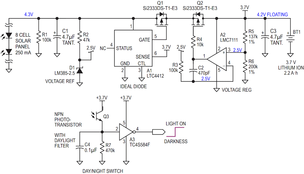
Jim Wilber looked at my design for a battery charger and sent me some suggested changes. He suggested using the LTC4412 ideal diode IC to switch off the current path from the solar cell to the battery in darkness. He also noted that the 2.5 V regulator from Seiko I had selected was no longer in production and suggested using the shunt reference. I think his suggestions made a lot of sense.
In my design, in dark conditions, the first MOSFET Q1 would not turn off until well after the point where the solar panel no longer produces current, allowing some leakage current to flow from the battery into the solar panel. I have included these changes in the circuit shown in Figure 7. I also included a day/night sensor which can be used to turn on a light at night. The phototransistor should be the type which is colored violet which contains a daylight filter.
 |
|
| Figure 7. | Schematic diagram of the charger. Version 2. |
The LTC4412 ideal diode from Linear Technology monitors the voltage from the solar cell and the battery. When the voltage from the solar cells is 20 mV higher than the battery, the output turns on the p-channel device Q1. In darkness, when the solar cells are no longer producing current, the voltage from the solar panel will be less than the battery. The ideal diode IC A1 will then turn off the transistor Q1, blocking the current path from the battery to the solar panel. In a similar fashion, in darkness, the 2.5 volt reference will drop to a lower voltage, being starved of current from the solar panel, turning off the voltage regulator circuit. The result is that Q2 is turned off hard. With both devices turned off, no current flows into or out from the solar panel. As in the last circuit, the op Amp A2 limits the charging voltage across the lithium ion battery to 4.2 V when the solar panel supplies current.