This isolated potentiometer module provides isolated analog (0−3.3 V from a 10K pot) and isolated switch inputs (via PC817 optocouplers) for industrial use. It uses a LOC110 linear optocoupler (3750 V isolation) and an isolated DC-DC converter for a single 5 V supply.
This is an Isolated potentiometer module that integrates a LOC110 linear optocoupler, an isolated DC-DC converter, an onboard 10K linear potentiometer, 2 × tactile switches, 2 × PC817 optocouplers, and supporting circuitry. It is designed for reliable use in VFD drives, process control, PLCs, automation systems, and other industrial applications where isolated analog signals and isolated switch inputs are required.
The two tactile switches are connected through two PC817 optocouplers, ensuring isolated operation. By default, outputs C1 and C2 remain high, and transition low when a switch is pressed.
Thanks to the onboard isolated DC-DC converter, the module operates from a single 5 V DC supply, simplifying system integration. With the full rotation of the potentiometer, the output provides a 0–3.3 V DC isolated analog signal, fully isolated from the potentiometer input.
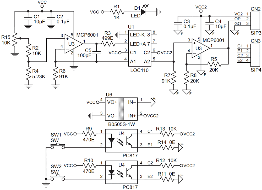
At the core of the design is the LOC110 linear optocoupler, which provides 3750 V isolation. The MCP6001 op-amp (U2) functions as a closed-loop servomechanism, sensing the photodiode current and driving the optocoupler’s LED to maintain accurate linearity. A second MCP6001 (U3) further conditions the phototransistor output. An onboard power LED (D1) indicates the active input-side supply.
The LOC110 incorporates an infrared LED optically coupled to two photodiodes. The feedback photodiode stabilizes the LED current, compensating for nonlinearity, time drift, and temperature variations, while the output photodiode delivers a highly linear, isolated analog signal.
This architecture ensures wide bandwidth, robust input-to-output isolation, and excellent servo linearity.
Features
- Single 5 V DC supply operation
- Onboard 10K linear potentiometer
- On board 2 tactile switch
- Integrated isolated DC-DC converter
- Power status LED indicator
- 0–3.3 V DC isolated output
- PCB dimensions: 47.15 × 35.08 mm
- 4 × 3 mm PCB mounting holes
Schematic and connections
Figure 1 shows the schematic diagram of the device.
 |
|
| Figure 1. | Schematic diagram of an isolated module. |
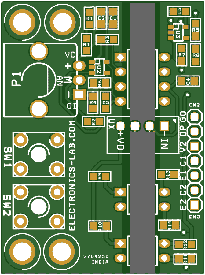
The CSV project files can be downloaded from the link in the Downloads section. The components placement is shown in Figure 2.
 |
|
| Figure 2. | The components placement of an isolated module. |
Table 1 shows the bill of materials.
| Table 1. | Bill of materials | |||||||||||||||||||||||||||||||||||||||||||||||||||||||||||||||
|
||||||||||||||||||||||||||||||||||||||||||||||||||||||||||||||||
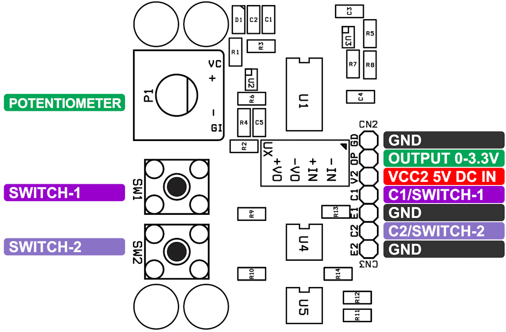
Figure 3 shows the device connection diagram.
 |
|
| Figure 3. | The module connection diagram. |
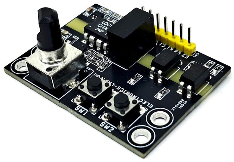
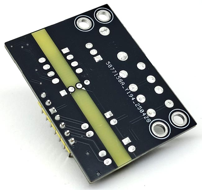
Figure 4 shows the assembled PCB board.
|
|||
| Figure 4. | Assembled PCB board of the module. | ||
Materials on the topic
- Datasheet Littelfuse LOC110
- Datasheet Microchip MCP6001
- Datasheet First Silicon PC817
- Datasheet Mornsun B0505S-1WR3