Charles Wenzel
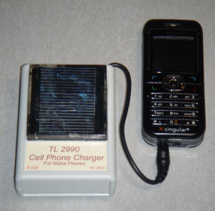
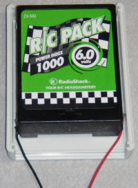
This little gadget uses a small 3 volt solar cell to charge a 6 volt NiCad battery pack which, in turn, may be used to charge many models of cell phones and other portable devices. The circuit "scavenges" energy from the solar cell by keeping it loaded near 1.5 volts (maximum energy transfer value) and trickle charges the internal battery pack with current pulses. The simple circuit isn't the most efficient possible but it manages a respectable 70% at 100 mA from the cell and 30% when the cell is providing only 25 mA which is actually pretty good without going to a lot more trouble or using more exotic components.
Note:
This circuit is intended for using a low voltage cell to charge a higher voltage battery. Don't use it to charge a battery at the same or lower voltage than the cells generate. The circuit needs a battery load to work properly. Different models of phones have different charging requirements and this charger may not work with all models.
| Ref. | Description |
| PC1 | 3 volt solar cell from a sidewalk solar light |
| C1 | 22 uF, 10 volt (values not critical) |
| C2 | 100 pF, any voltage or type, typically ceramic |
| C3 | 10 uF, 16 volt or more for higher voltage battery |
| R1 | 1.5 k, any type |
| R2 | 3.9k, any type |
| R3 | 10k, any type |
| R4 | 180 ohm, any type |
| R5 | 4.7k, any type |
| R6 | 10 ohm PTC (see text). |
| L1 | 50 to 300 uH (see text) |
| D1 | 1N5818 schottky rectifier, just about any will do. |
| Q1 | 2N4403, or similar |
| Q2 | 2N4401, or similar |
| J1 | output jack |
| B1 | 6 volt NiCad battery w/fuse |
 |
 |
Here is how it works:
When the voltage on the emitter of Q1 rises a little over 1.5 volts, both transistors turn on quickly, snapping on due to the positive feedback through R5 and C2. The current increases in L1 through Q2 until the voltage across the cell drops somewhat below 1.5 volts. The circuit then switches off quickly and the voltage on the collector of Q2 jumps up, turning on D1, allowing the inductor current to flow into the battery. Once the inductor has discharged into the battery, the process starts over. The circuit can charge higher voltage batteries without any circuit changes since the voltage will jump up quite high on the collector when the transistors turn off. The circuit should not be operated without a battery attached. For a little more efficiency, increase R5 in proportion to the voltage increase on the battery. (For example, double R5 for charging a 12 volt battery.) A NiCad battery was chosen because they are particularly forgiving of overcharging, simply converting the excess current into heat.
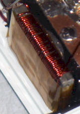
The photocell was salvaged from an inexpensive solar sidewalk illuminator and it has an open-circuit voltage of about 3 volts and supplies about 100 mA in bright sunlight. The circuit can handle more current but avoid cells that supply more than 250 mA. The inductor should have a low resistance winding but a surprising number of cores will work fairly well. The core in the prototype is actually a piece of ferrite antenna rod chosen simply to fit in the extremely limited confines of the package. Another unlikely inductor that worked well was 10 turns on one of those 1" long, 1/2" diameter large ferrite beads often used for power line baluns! The value of inductance isn't critical, perhaps between 40 and 300 uH and during proper operation there will be a pulse waveform on the collector of Q2 with several 10s of microseconds period. This prototype operates at about 40 uS as shown and the inductance measures about 50 uH.
For experimenting with cores or other circuit values, replace the NiCad battery with a zener of the same voltage and replace the solar cell with a 3 volt power supply with a series resistor, about 22 ohms to simulate moderate sun. Measure the current in the zener and compare that power (zener current times zener voltage) to the power coming from the power supply (3 volts times power supply current) to see how the circuit is doing. When the power in the zener is over half the power from the supply, the inductor is good enough.
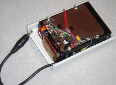
It is mandatory that a fuse be added near one of the terminals of the battery! (See the little green 2 amp fuse along the bottom edge of the battery.) Battery packs can supply dangerous current levels! Keep the lead from the fuse to the battery terminal as short as practical. I had to change this fuse; I'm glad it was there!
In addition to the fuse a 10 ohm PTC was added in series with the output to limit the available power but also to allow the unit to charge my Nokia phone which doesn't like a very low impedance battery as a charging source. (The phone simply displays "battery not charging".) I have a few thousand of those, if you need a couple (charles@wenzel.com). The PTC is actually soldered directly to the copper board and one end of the fuse connects directly to the top side.
Don't copy my assembly technique! First of all, I had to cut all the mounting posts out of the case to get the battery to fit and it is held in by glue. Notice the silver nuts soldered onto the PCB for securing the cover! Secondly, there is very little height for the circuitry so everything is pressed down flat against a piece of copper clad board using little bits of board for the connections. That's a fine technique but this prototype was just too tight for comfort. Third, I had to search a while to find an inductor that would fit! All the room was used up before I got to one of the larger parts! Having said all this, the final unit is very compact and solid but there was too much luck involved!
It works great! I simply leave it on my dash until I need it. I've charged several Nokia phones without a problem. It is actually more convenient than a cigarette lighter adapter because it can travel with the phone and it doesn't need sunlight to charge the phone. I will say that the thing charges my phone suspiciously fast and I wonder if I should increase the output resistance. Fast charging cell phone batteries shortens their life, if I understand correctly. Most phones have sophisticated internal charging circuits but I suspect the manufacturers sacrifice battery life for fast charging. It might simply be that my phone hasn't been significantly discharged since I built the charger.