Elio Mazzocca
Capacitive sensing is a versatile technique that can solve a difficult sensing problem in a surprisingly simple manner. For example, it can be used to turn a liquid-metal thermometer into the sensing element of a thermostat. Such thermometers are available with maximum temperatures ranging from 50°C to 360°C, allowing this simple thermostat design to work for a wide variety of temperature ranges.
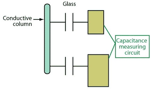
The design works by sensing the capacitance between two conductive foil band electrodes placed on the outside of the thermometer. When the metal column has risen to reach the upper electrode, positioned to correspond to the desired setpoint temperature, the structure forms the equivalent circuit shown in Figure 1.
 |
|
| Figure 1. | The conductive metal inside a thermometer forms capacitive connections to foil electrodes wrapped around the outside and completes the circuit between the electrodes. |
Each electrode is one plate of a capacitor, the metal column is the second plate of both capacitors, and the glass tube is the dielectric between the plates. A microcontroller running charge-sensing software monitors circuit capacitance to determine when the metal column (hence temperature) has reached the setpoint.
This technique only works with conductive liquids, though. Because the European Union’s Restrictions on Hazardous Substances (ROHS) initiative discourages the use of mercury, designers should choose thermometers using a non-toxic gallium-indium alloy.
As long as the column is distant from the threshold, the circuit is essentially open-circuited. When the column reaches the top electrode, the two capacitors become connected together. The upper electrode achieves maximum capacitance when the column fills the space under the foil.Because the column of a 0°C to 50°C thermometer may be as thin as 0.2 mm, this capacitance will only be a fraction of a picofarad.
Thus, the electrode should be placed with its top just below the setpoint so that charge detection can work with the maximum signal. A practical length for the top electrode is about 10 mm. To maximize detection sensitivity, the bottom electrode should be as large as possible (30 mm in this example). A vertical gap in the top electrode provides an additional visual indication of the temperature at the setpoint.
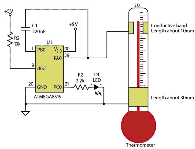
The complete thermostat uses an ATMEGA8515 microcontroller (Fig. 2) running charge sensing software from the Atmel demonstration library . This software is configurable for keys, rotors and sliders, and other parameters, allowing designers to optimize for measurement sensitivity, threshold, and other low-capacitance detection requirements. It can also be configured for multiple detectors with adjacent key suppression (AKS).
 |
|
| Figure 2. | A microcontroller running charge-sensing software can use the electrode-wrapped thermometer as the basis of thermostatic control. |
The demo software used in this design emulates hardware capacitive sensing devices such as the QT110 series. (The author’s software, IFD2438Mazzocca.c. The software refers to an Atmel library routine, available as IFD2438Atmel.h.)
These hardware devices offer automatic recalibration, however, so they cannot be used for thermostat operation. The recalibration would continually zero out the signal if the column remained above the top electrode (i.e., the signal remained at the detection threshold) for any period longer than the recalibration time—typically 10 seconds to 1 minute. The software also allows this recalibration to be removed, though, eliminating the problem. Adding the lines of code below to the demo software turns charge sensing into thermostat operation:
DDRC = 0xFF; //PortC = output
PORTC = 0x0; //all O/Ps lo

if(qt_measure_data.qt_touch_status.sensor_states[0])
{PORTC |= (1<<0); } //bit 0 hi

else { PORTC &= ~(1<<0); } //bit 0 lo
In any practical application, the detection circuitry will need to be temperature stabilized. This can be accomplished by using a temperature-stable power supply for the microcontroller and a low temperature-coefficient charge capacitor (C1). Movement of the connecting leads to the electrodes should be minimized because their stray capacitance will add to the column capacitance and their movement would modify the detection threshold.