In many situations, designers must control the phase of an output signal in order to make certain circuits work properly. At low frequencies, an op amp can be used to vary the phase. But as the frequency gets into the RF range, output phase control gets a bit more complex.
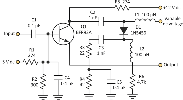
The Figure 1 illustrates an example of how to control the phase at higher frequencies. I randomly chose 70 MHz for the circuit, but any frequency can be implemented. The beauty of this circuit is that a table can be calibrated with a microcontroller, and a digital-to-analog converter (DAC) can be used to set the variable dc voltage.
 |
||
| Figure 1. | The variable dc voltage applied to this circuit changes the diode’s capacitance in a predictable way. Thus, the phase of the output voltage can be controlled. |
|
As this dc voltage is varied, D1 reacts to the dc bias by changing its capacitance accordingly. This sets the output with a different phase than its input. The Table gives the values of the phase difference versus the variable dc voltage.
| Table 1. | Phase Difference vs. Variable DC Voltage |
||||||||||||||||
|
|||||||||||||||||
The circuit has low-impedance output, so careful design is needed to interface the output. One can cascade many of these circuits to accomplish a full 360° rotation in very accurate settings. Note that temperature differences will change the value of the capacitance of the 1N5456, so a very precise calibration is needed to use this circuit in practical environments.