Wayne Ryder
Electronic Design
The prescaler described here connects to the front end of a 100-MHz frequency counter to extend its coverage range to 10 GHz. The circuit is a far less expensive way to measure frequencies above 100 MHz than buying a 1- or 10-GHz frequency counter. The divider was built inexpensively. Creating this low-cost prescaler required some tradeoffs, and some rules were not followed (discussed later in the article).
When you use this or any similar prescaler, the two least significant digits will be lost. If the frequency being measured is 9,123,456,789 Hz, the frequency will be displayed as 9,123,456,7XX Hz. Having the last two digits not shown shouldn’t be a problem, considering the frequencies being measured.
A second source of error is the frequency counter itself. The counter should be tested for accuracy. You can do this by connecting the output of a 100-MHz signal generator to the counter and counting for one or 10 seconds. Also, the counter time-base oscillator should be calibrated using WWV or a similar source.
IC1 is a 10-GHz, divide-by-2, static divider; IC2 is a 7-GHz divide-by-5; and IC3 is a 1-GHz divide-by-10 (Figure 1). All components are mounted in a cast aluminum box measuring about 7.5 by 4.7 by 2 in. (190 by 120 by 50 mm) deep. Electronic components are mounted on 0.062-in. (1.57-mm) double copper-sided printed-circuit board (PCB) that’s 7 by 2 in. (175 by 50 mm). The dimensions of the box and board aren’t critical.
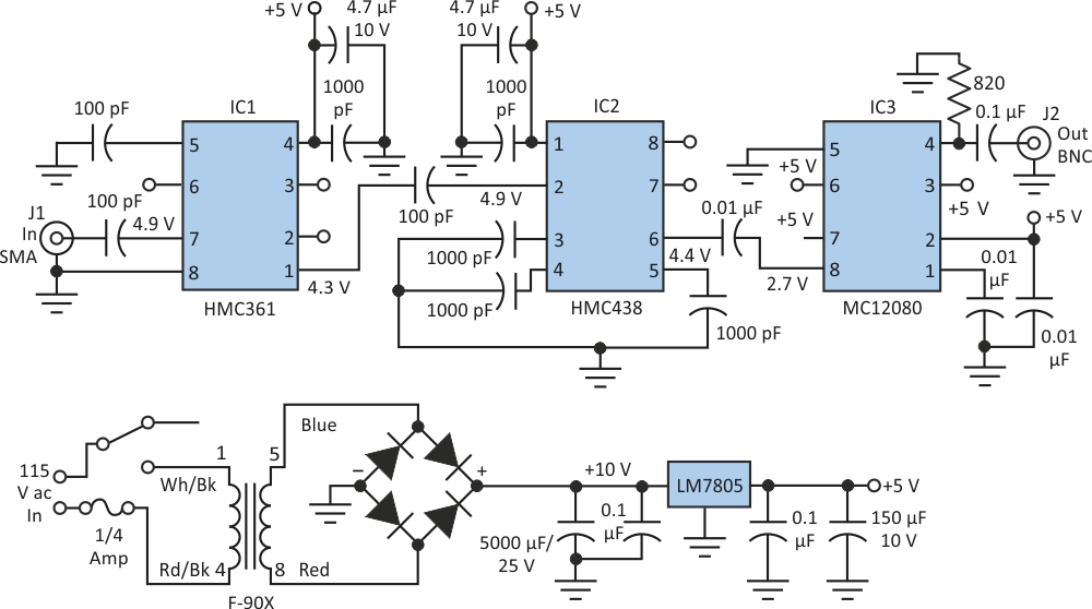 |
||
| Figure 1. | With a few acceptable tradeoffs, this inexpensive prescaler circuit permits a 100-MHz frequency counter to measure up to 10 GHz. The power-supply circuitry is shown separately at the bottom. |
|
J1 was soldered to the top and bottom of the PCB. This ensures mechanical stability for the input capacitor and IC1. For further support, the hole in the box is only slightly larger then J1. A recess was milled around the hole to be able to screw on an SMA connector. Protection diodes at J1 would degrade sensitivity, so they were omitted. IC1’s bottom was not grounded as it should be.
A Hittite evaluation board was purchased for IC2 because of the close spacing of the leads: 0.025 in. (0.65 mm). Evaluation boards are available for IC1 and IC2 at $164 (U.S.) each from Hittite. A set of ICs is $26 (U.S.). A PCB would simplify construction and reduce costs. For a prescaler that goes only to 1.3 GHz, consider building one with IC3 only. Although IC3 is rated to work at 1 GHz, it works okay at 1.3 GHz.
Power-supply current is about 170 mA. Before connecting the prescaler electronics, verify that the input to the 7805 voltage regulator is 8 to 15 V and the output is +5 V. All capacitors below 0.1 μF are chip caps.
The prescaler has some limitations. Its lower frequency limit is about 200 MHz. Also, IC3 oscillates with no input. And, dynamic range is somewhat limited (see Table 1). The sensitivity limitations are probably due in part to construction methods.
| Table 1. | Prescalar Sensitivity | ||||||||||||||||||||||||||||
|
|||||||||||||||||||||||||||||
| *Never exceed +10-dBm input | |||||||||||||||||||||||||||||
The prescaler has been working for over a year, performing a variety of tasks.