Lee Goldberg, Electronic Products
Whether you are an embedded design pro or a newbie hacker, you will appreciate how the Arduino open-hardware platform’s analog input and output channels make it easy for your projects to reach out and touch the “real world”. The compact modules provide easy access to the MCU’s multi-channel inputs, which can be used to monitor voltages and read a wide variety of analog sensors or sample waveforms.
While the MCU’s digital-to-analog converter has relatively modest resolution and conversion speeds, it is well-suited for many common applications ranging from lighting or motor control to driving an amplifier’s gain bias. This article will introduce the hardware and software resources that form the basis for Arduino’s analog functions and show you how to use them in your next design.
If you are not familiar with Arduino, you can learn all about it from the TechZone article “Arduino Open Source Platform Unleashes Creativity”.
Born for analog
In keeping with its philosophy of making it easy to apply digital technology to real-world applications, the Arduino hardware platform was designed to make the most of the analog capabilities built into Atmel’s versatile ATmega 8-bit MCU family. All variants of the ATmega used in Arduino platforms are equipped with an on-chip, multi-channel channel analog-to-digital converter (ADC). The ADC has 10 bit resolution, capable of producing up to 15,000 samples/sec in the form of integers from 0 to 1023. Most AVR MCUs support 6 analog input channels although some variants support 8 and 16 inputs. While the primary function of the analog pins is to read analog inputs, the analog pins can also be configured as digital general purpose input/output (GPIO) pins. Should they be needed, the analog pins have selectable pull-up resistors, which can be configured in a manner identical to the pull-ups on the MCU’s digital pins.
Although some AVR MCUs are equipped with digital-to-analog converters (DACs), the family members on the present generation of Arduino boards produce their analog outputs by rapidly toggling their digital I/O pins to produce pulse width modulated (PWM) signals. The duty cycle of each PWM output’s 490 Hz (approx.) square wave can be programmed to deliver an equivalent RMS voltage between 0 and 5 V in 256, 2 msec increments (Fig.1). Although somewhat limited in their capabilities, the Arduino’s outputs can be used to for many tasks such as driving LEDs or controlling motors.
 |
|
| Figure 1. | Arduino’s digital GPIO pins can serve as analog outputs by using Pulse Width Modulation (PWM) techniques (Courtesy of Arduino.cc). |
Most Arduino boards provide easy access to the MCU’s analog (and digital) I/O signals through female pin connectors at the edge of the board. The number of analog channels and their physical pin assignments vary according to the particular MCU being used and the board’s from factor, but many variants follow the pin-out conventions used by popular “Official” designs, such as the Uno (Fig.2), Mega, and Nano.
.jpg) |
|
| Figure 2. | The Arduino Uno (rev3) board’s analog inputs (A0-A5) and analog PWM outputs (Digital 3, 5, 6, 9, 10, and 11) are physically accessed via standard header pins at the edge of the board (Courtesy of Arduino.cc). |
Developing code with analog I/O functions is also easy since the programming language supported by the Arduino IDE includes a set of native Analog I/O commands. These instructions enable reading analog inputs, generation of analog (PWM) outputs, and configuration of the A/D converter reference voltage.
Reading analog inputs
Hitching up the Arduino’s analog inputs to a real-world application is fairly straightforward, but requires some attention to selecting the proper voltage reference source for the AVR’s A/D converter. It can use either a DEFAULT, INTERNAL, or EXTERNAL reference voltage to determine the top of its input voltage range. In DEFAULT mode, the MCU uses the output of the on-board power supply regulator as a reference. Depending on the particular Arduino board being used, this is either 5 V or 3.3 V.
The INTERNAL mode uses the AVR’s on-chip precision reference source. The source’s voltage varies between specific devices, but is usually either 1.1 V (for the ATmega168 or ATmega328) or 2.56 V (on the ATmega8 and Mega series). The EXTERNAL mode allows you to connect an external reference voltage to the AREF pin through a 5K resistor. The AREF pin has an internal 32K protection resistor which acts as a voltage divider with the external 5K resistor. This means that, for example, 2.5 V applied through the resistor will yield 2.5 * 32 / (32 + 5) = approximately 2.2V at the AREF pin.
Reading analog voltages using Arduino programming language involves selecting the reference source using analogReference(type) and then invoking a read analogRead(pin) where (pin) indicates the header pin number you wish to sample. Once selected, the Reference type remains constant until otherwise programmed. Although AVR MCUs support conversion rates of up to 15k samples/sec, the Arduino hardware/software environment typically limits this to around 10k samples/sec.
Creating PWM analog outputs
Generating an analog voltage on one of Arduino’s PWM pins requires configuring the desired pin as an output using the pinMode(pin, mode) command and then invoking an analogWrite(pin, value), where (pin) indicates the header pin you wish to output to and (value) is the fraction of the reference voltage to be generated (in increments of 1/255). Once configured, the pin will generate a steady 490 Hz square wave with the specified duty cycle until the next call to analogWrite() (or a call to digitalRead() or digitalWrite() for the same pin is issued).
The I/O pins can support drive currents of up to 40 mA, so they can drive moderate-sized LED arrays directly. For higher-powered lighting or DC motors, the analog output can be used to drive a power transistor or bridge circuit. For more demanding applications, the output can be filtered using a simple R/C network and used as the control voltage for an amplifier or current source.
More analog tricks
Some AVR MCUs (including the MEGA8 and MEGA168) have an internal comparator which can compare an input voltage against another external input, a voltage generated by one of the PWM outputs, or the reference device’s internal reference voltage. The comparator’s output can be polled or used to trigger an interrupt. While it involves more software, an interrupt-driven arrangement lets the processor sense an under-/over-voltage condition without having to repeatedly sample an analog channel. This can be very handy for everything from adjustable-threshold motion detectors and shock sensors to biomedical monitoring.
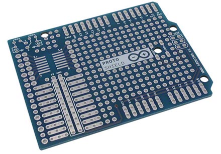
For Arduino boards whose MCUs do not have an internal comparator, it is relatively easy to add a an external device such as a LM741, LM339N, or TLC3704 in the “kluge” area provided on some Arduino boards. If your platform lacks a spot for user-supplied circuitry, it can be added using an inexpensive prototyping shield card (Fig.3)
 |
|
| Figure 3. | Prototyping shield cards make it easy to add your own analog (or digital) I/O to nearly any standard Arduino board (Courtesy of Digi-Key). |
Summary
Arduino’s low cost and versatility has built a loyal following among commercial hardware developers. The Arduino hardware platform was designed to make the most of the analog capabilities built into Atmel’s ATmega 8-bit MCU family. All variants of these MCUs are equipped with an on-chip multi-channel analog-to-digital converter (ADC). This article is intended as an introduction to the hardware and software resources that form the basis for Arduino’s analog functions and a jumping off point for engineers who can use these functions in upcoming designs. To that end we discussed reading analog inputs, creating PWM analog outputs, and adding external analog I/O.