Sam Sattel, Autodesk
 |
Ladies and gentlemen, the next major update for Autodesk EAGLE has landed! This release is all about upgrading the professional tool that you know and love with some much needed intelligence and accessibility. Inside you’ll find new tools that help you cut out the busywork and focus on what really matters, designing professional electronic devices. We’ve got new features for routing, schematic capture, and design management that will level up your electronics design game. Here’s what’s new in this release:
Quick Route
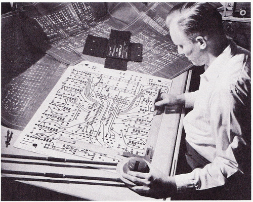
First, a quick walk down memory lane. The first commercially available ECAD tool came about in the 1980s. Before then it was all about tape and mylar. With ECAD, we took what was once a physical process of routing and just transferred it into the digital domain. The way we have been routing has largely remained unchanged (Figure 1).
 |
|
| Figure 1. | Drawing a printed circuit board with tape and mylar before EDA arrived. Yep, we’re still doing this, just with a mouse. (Image source: autodesk.com). |
Today, this is a bit of a problem. We’re still manually routing PCBs the same way we did 30 years ago, but our board layouts have changed dramatically. Complexity has expanded, but our process has stalled. With Quick Route, we decided it’s time to move designers beyond the manual point-to-point mentality into a more intelligent way of working.
What it does
Quick Route lets you route single nets, multiple nets and differential pairs in rapid-fire with a single mouse click. No, this is not another autorouter, this is an intelligent routing aide. You get to decide which nets get routed, and Quick Route does the manual busywork of connecting that net from node to node for you.
With Quick Route we’ve designed a system that analyzes all of your nets holistically before deciding how to make a connection. How does this manifest? When Quick Route connects a net, the results look incredibly natural and human. You get the beauty of a flowing board layout without all of the manual busywork.
Today, Quick Route supports single-click finish for:
- Airwires
- Single or multiple nets
- Differential pairs
- Trace smoothing
How it works
Enter routing mode and you’ll discover four new Quick Route options to work with:
 |
- Quick Route Airwire
This mode completes airwire connections instantly in a single click for individual signals or differential pairs. There are two methods for using this mode. You can either click the beginning of an airwire connection and have it auto complete. Or you can start routing an airwire manually, and press Enter on your keyboard at any time to have Quick Route take over and complete the connection (Figure 2).
 |
|
| Figure 2. | Quick Route Airwire completes airwire connections instantly in a single click for individual signals or differential pairs. |
- Quick Route Signal
Similar to Airwire, Quick Route Signal will complete an entire net connection in a single click for either individual nets or differential pairs. Again you can either let Quick Route take care of the job completely, or start routing your net and press Enter to complete the connection (Figure 3).
 |
|
| Figure 3. | Quick Route Signal completes will complete an entire net connection. |
- Quick Route Multiple Signals
Ready to throw a real challenge at the Quick Route engine? Left-click and drag to select multiple pads, then press Enter on your keyboard and all the signals are completed, instantly. You can route either multiple, unrelated nets or a logical bus, the choice is yours (Figure 4).
 |
|
| Figure 4. | Quick Route Multiple Signals can route either multiple, unrelated nets or a logical bus. |
- Smooth Signal
Got some traces you want to clean up? The Smooth Signal mode will automatically smooth out one or multiple traces by looking for overlapping segments and excess length (Figure 5).
 |
|
| Figure 5. | Smooth Signal mode will automatically smooth out one or multiple traces. |
Quick Connect
We’re all familiar with the challenging process of designing a schematic. The hardest part isn’t finding the parts or placing them. It’s spending an insane amount of time wiring every pin and making labels.
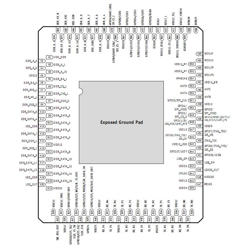
Take something like a 2K pin BGA (Figure 6). Breaking out all the pins and adding labels can literally take an entire workday. And what happens if you make a typo on a label or connect one of those pins incorrectly? This kind of work, while it’s something we’ve all accepted as part of the job, just isn’t worth our time. With Quick Connect, we’ve done away with the manual and error prone process of wiring schematic symbols and creating net labels.
 |
|
| Figure 6. | This one might take a while. |
What it does
Place a symbol or bus down on a schematic and Quick Connect will automatically break out every pin and its label. This feature is priceless when working with high pin-count components. We’ve all spenta colossal amount of time breaking out BGAs or ICs, only to find out we made a simple mistake on a label or connection. These are all mistakes of the past.
How it works
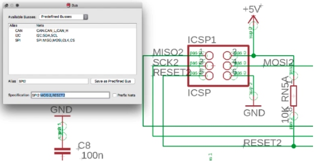
EAGLE now has the ability to save buses for future reuse. By default there’s CAN, I2C, and SPI buses created out of the box. Need to create a new one? Select all of your desired signals, create a bus, and the signals get automatically added for you (Figure 7).
 |
|
| Figure 7. | Eagle 9.0 now has the ability to save buses for future reuse. |
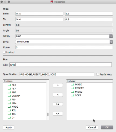
If you’re just wiring a bus without configuring it beforehand, all of the required signals can be added in the Bus Properties dialog. Give that bus a name and you have yourself a saved bus (Figure 8).
 |
|
| Figure 8. | Required signals can be added in the Bus Properties dialog, then give that bus a name and you have yourself a saved bus. |
Bus Breakout
Need to break out all the signals on a bus you just created? Right click the bus and check out the new Breakout Bus options. Quick Connect will automatically add your signals with labels (Figure 9).
 |
|
| Figure 9. | Bus Breakout: Quick Connect will automatically add your signals with labels. |
Signal Breakout
Let’s throw something more challenging at Quick Connect, like a 30+ pin integrated circuit. Imagine having to break out every pin and add labels manually on a symbol like this. That’s going to take you at least 30 minutes at a minimum.
Right click to use the new Breakout Pins feature, and watch what happens, instantly (Figure 10):
 |
|
| Figure 10. | Eagle 9.0 Signal Breakout function. |
Connect Pins to Bus
How about connecting all of the pins from your IC to a bus? Another manual process that takes way too much time. With a preconfigured bus filled with signal names that match our IC, we can make this process happen instantly (Figure 11):
 |
|
| Figure 11. | Connect Pins to Bus with Quick Connect function in Eagle 9.0. |
Design Manager
Navigating a modern PCB layout is anything but easy. Finding what you need visually through a dense maze of traces, vias, and components makes for seriously tedious work. We created the Design manager to give you greater visibility and control over your PCB layout from a single panel in Autodesk EAGLE.
What it does
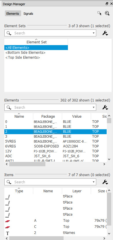
You can think of the Design Manager like your master console for all things PCB design. Need to select a specific set of nets and rip them up? You can do that from here. Or maybe you need see only blind and buried vias? The Design Manager has you covered (Figure 12).
There are a variety of actions you can do from this one panel in EAGLE, including:
- Select single or multiple nets, and then route them with Quick Route
- Select single or multiple nets and rip them up
- Select single or multiple objects and highlight them on your board
- Select any object and apply any command
- Filter and sort objects to your heart’s content
 |
|
| Figure 12. | Design Manager panel in Eagle 9.0 |
How it works
When you open EAGLE 9 for the first time you’ll notice the Design Manager nestled on the right side of your interface. If this placement isn’t to your liking, no worries, you can dock the panel to the left side of the UI, float it around, or get rid of it entirely. Happen to close it accidentally? Open it again from View > Design Manager.
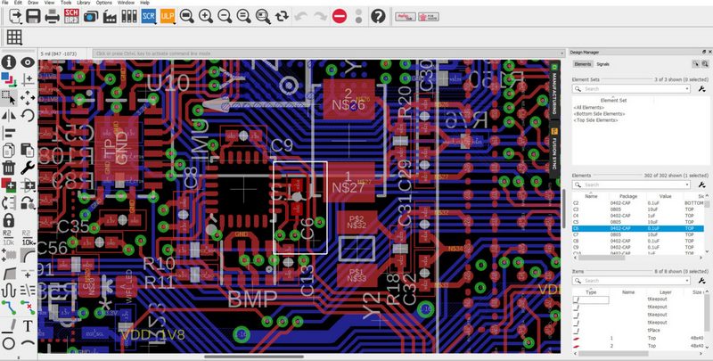
The Design Manager has two primary views to work from, Components and Nets. For the component view, there are a few standard component groups that help to quickly filter parts by the top and bottom side of your board. You can also search for parts manually. Once a component is selected in the Design Manager, it gets highlighted on your board (Figure 13).
 |
|
| Figure 13. | Once a component is selected in the Design Manager, it gets highlighted on your board. |
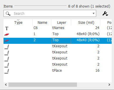
A selected component will also be broken down into its individual elements in the Design Manager. This gives you greater visibility over individual silkscreen and pad features without having to open the library editor (Figure 14).
 |
|
| Figure 14. | Selected component will also be broken down into its individual elements in the Design Manager. |
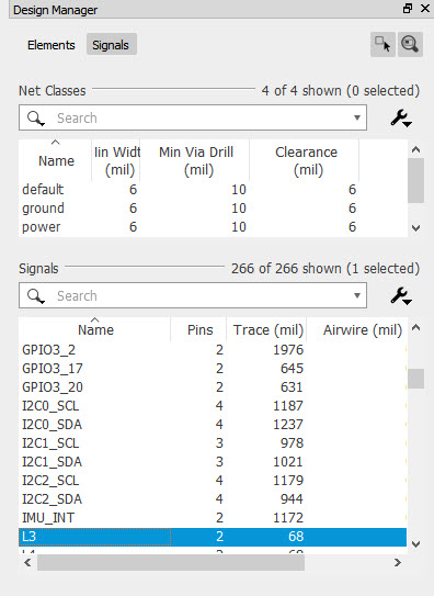
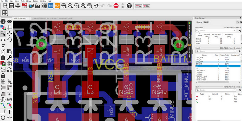
The real power of the Design Manager comes when working with nets. You can either search for nets in the search bar, or filter by your preconfigured net classes (Figure 15).
 |
|
| Figure 15. | In Design Manager you can either search for nets in the search bar, or filter by your preconfigured net classes. |
Like the component view, selecting a net will highlight it on your board layout. Right-click and you’ll get options to select the net in the editor, rip it up, or route with Quick Route (Figure 16).
 |
|
| Figure 16. | Once a net is selected in the Design Manager, it gets highlighted on your board. |
Want to route multiple nets or differential pairs without ever laying hands on your PCB layout? Select them from Design Manager, right-click, and choose Quick Route. The same holds true for ripping up nets. What you used to do manually in your PCB layout editor can now be done automatically in the Design Manager (Figure 17).
 |
|
| Figure 17. | From Design Manager you can route multiple nets or differential pairs without ever laying hands on your PCB layout. |
We’ve also expanded the riprup options available for a net within the Design Manager. Selecting a net from the Items section will allow you to ripup either traces and vias, connected copper, or connected copper on the same layer.
Get EAGLE 9.0 Now
We’re incredibly excited to push electronics design forward with EAGLE 9, leaving behind busywork that none of us will ever miss. Whether you’re just getting started with electronics design or you’re a seasoned veteran, we all share the same pains of dealing with manual routing, schematic wiring, and just plain ol’ navigating our designs. The new, intelligent features in EAGLE 9.0 help you stay focused on what really matters, creating professional electronic designs.
For our EAGLE Subscribers, this update will be ready and waiting to download the next time you start your software.