Cesca Fleischer, Michelle Stone, Lourdes Vasquez
autodesk.com
Autodesk is constantly improving its software products. Eagle CAD software was no exception. In this article, we will consider the main innovations and improvements in the latest versions, starting with 9.3, which allow us to speed up, simplify and improve the design of printed circuit boards in CAD Autodesk Eagle.
The Ultimate in PCB Collaboration
PCB design collaboration is now redefined in EAGLE with the new Fusion Team button. This new button solves your documentation needs, your publishing needs, global sharing and collaboration needs, redlining needs, and provides extended viewing like never before. We all know we interface with people outside of our organization or even computer, this new integration revolutionizes how we work together. Making the world of engineering smaller.
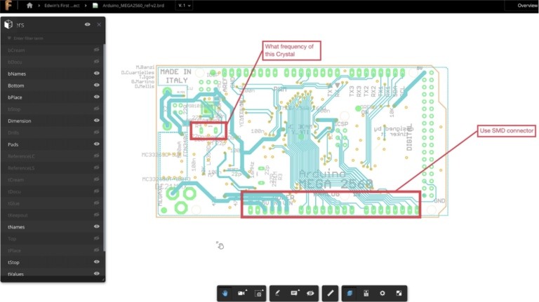
Fusion Team supports viewing and annotating EAGLE design files, so even team members that don’t use EAGLE can provide suggestions on the electronic design. It also integrates seamlessly with Fusion 360, so your electronics designs, manufacturing designs, and mechanical designs can all live in one place.
What it does:
Designed to make it easy for the engineer, project manager and entire team to easily share and review design data. Simple enough to use so that users with little to no experience with EAGLE can still join in adding markups and comments (Figure 1).
 |
|
| Figure 1. | Fusion Team supports viewing and annotating EAGLE design files. |
How it works:
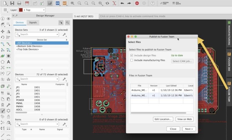
Push your EAGLE design and manufacturing files to Fusion Team and then send invites to team members to start collaborating. Fusion Team allows you to easily control visible board layers, highlight components and will also version these releases so your design will be documented every step. When you push your EAGLE design to Fusion Team you’ll automatically get a 3D view of your circuit board since the same cloud backend connects EAGLE and Fusion 360. Additionally, if you include the manufacturing files, you can form a release of the design in which the manufacturing data is completely in step with the design files. Fusion Team will version these releases so your design will be documented every step of the way since the notations are also versioned (Figure 2).
 |
|
| Figure 2. | Push your EAGLE design and manufacturing files to Fusion Team and then send invites to teammembers to start collaborating. |
Try it yourself:
Click the Fusion Team button and then select if you want to push just the design files, or the design files and manufacturing files, then click ‘OK’. The Fusion Team viewer fully understands EAGLE file format so you can easily control what layers are visible and make annotations for design reviews and recommendations (Figure 3).
It’s important to mention that this doesn’t change how files are saved in EAGLE. Your local design data will not be changed or affected by pushing to Fusion Team. We are really excited about the workflows this integration will enable since it will allow teams to work more effectively together.
 |
|
| Figure 3. | The Fusion Team viewer fully understands EAGLE file format so you can easily control what layers are visible and make annotations for design reviews and recommendations. |
Filter Selection tool
What it does:
This new feature gives you more control over what’s included in your group selections and avoids accidentally moving the attributes of components not in the group. There are instances that moving a defined group will include attributes that are not intended to be moved. One solution is using the layers setting option and disabling the layer pertaining to those attributes. In this release, we’ve provided an easier and more efficient way of solving this issue (Figure 4).
 |
|
| Figure 4. | Filter Selection tool gives you more control over what’s included in your group selections. |
How it Works:
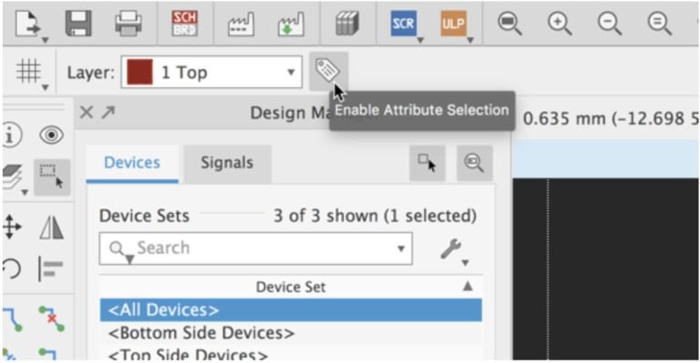
Now we’ve made a quicker way to filter attribute selections with the GROUP command. Activate the Group command, on the top parameters toolbar you’ll see the Enable Attributes selection icon. Clicking it will allow the >NAME and >VALUE text to be included when forming a group, you’ll see the selection crosshairs on the text when this option is active. Clicking the icon again will toggle the option and you’ll see that the selection crosshairs disappear from the >NAME and >VALUE texts. This feature gives you more control over what’s included in your groups and avoids accidentally moving the attributes of components not in the group (Figure 5).
 |
|
| Figure 5. | Filter Selection tool a quicker way to filter attribute selections with the GROUP command. |
Package Generator Improvements
Creating parts was once a long, time-consuming process. We made it easier and faster with the built-in Package Generator in Autodesk EAGLE. This go-to tool easily allows users to make complex component footprints and 3D models that are IPC compliant (Figure 6).
 |
|
| Figure 6. | Eagle 9.3 taken the package generator to the next level. |
Together with the 9.3 release, we have added new package calculators to the package generator as well as support for thermal pads on selected surface mount packages. The new supported package types are:
- Radial LEDs
- SON
- Through hole crystals
- Radial capacitors and inductors
We’ve taken the package generator to the next level and we know that it’s going to be saving you even more time when making your component libraries!
Simulation Improvements
This release welcomes a non-modal dialog for the SPICE simulator. We’re giving the SPICE simulator its own private window, not only to enable easier viewing but to allow for an interactive design flow between schematic and simulations. In previous versions of EAGLE, the spice simulator would block EAGLE which means that you couldn’t adjust your design while running the spice simulator (i.e. design, simulate, close sim, change design, sim etc.). This is no longer the case (now design, sim, change design, sim). In fact, the simulator window will detect when changes are made to the design and ask the user if they would like to update the simulation results with these changes.
For those of you who work with multiple monitors, this will be a boon to productivity since you can place the simulator window on a separate monitor. This is the first of several forthcoming improvements and we couldn’t be happier.