D Ramírez, S Casans, C Reig, AE Navarro, and J Sánchez
EDN
Although well-known to active-filter theorists and designers, GICs (generalized impedance converters) may be less familiar to analog generalists. Comprising a one-port active circuit typically comprising low-cost operational amplifiers, resistors, and capacitors, a GIC transforms capacitive reactance into inductive reactance and thus can substitute for an inductor in a filter that an RLC-transfer function describes. In addition, the flexibility of a GIC's input-impedance equation permits the design of virtual impedances that don't exist as physical components – for example, frequency-dependent resistance (Reference 1). The GIC, which its developers introduced 30 years ago, has seen its greatest application in ac-circuit and active-filter applications.
 |
||
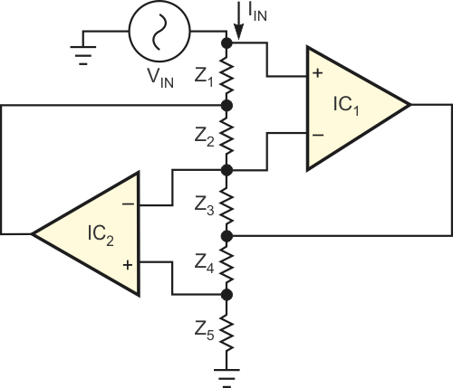
| Figure 1. | A classic generalized impedance converter provides a single-port impedance that appears at VIN. The schematic omits power connections for clarity. |
|
Figure 1 shows a classic GIC circuit in which the input impedance, ZIN, depends on the nature of impedances Z1 through Z5. The following equation describes the circuit's input impedance:
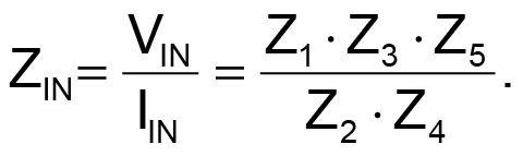
For example, if Z1, Z2, Z3, and Z5 comprise resistors R1, R2, R3, and R5, and Z4 comprises capacitor C4, then the input impedance, ZIN, appears as a virtual inductor of value LIN:
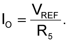
Figure 2 shows the GIC circuit in its dc configuration. When you consider the GIC circuit in a purely dc environment, you can envision new applications. For example, you could replace impedances Z1 through Z5 with pure resistances R1 through R5. Instead of an ac input-voltage source, connect a precision temperature- and time-stable dc reference voltage to the input port. A simple circuit analysis using ideal op amps for IC1 and IC2 shows that the reference input voltage, VREF, appears across resistor R5, and, as the following equation shows, a constant current, IO, flows through R5.
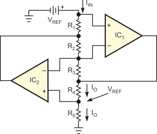 |
||
| Figure 2. | Replacing all of a GIC’s impedances with resistors creates a constant-current source. |
|
However, op amp C2's noninverting input diverts a small amount of current from the junction of R4 and R5, and IO thus also flows through R4. Selecting large values for R1, R2, and R3 helps minimize current drawn from the reference voltage. For example, the circuit can supply 2 to 10 mA to R4 and draw only a few tenths of a microampere from the reference source. Using tight-tolerance and low-drift components for VREF and R5 ensures the stability of IO. Applications include providing constant-current drive for Wheatstone-bridge and platinum-element sensors (Reference 2). In addition, you can replace R4 with a series of resistive sensors as in an Anderson loop (Reference 3).
References
- Franco, S, Design with Operational Amplifiers and Analog Integrated Circuits, Third Edition, ISBN 0072- 320842, WCB-McGraw-Hill, 2001.
- Ramírez, Diego, S Casans, and C Reig, "Current loop generated from a generalized impedance converter: a new sensor signal conditioning circuit," Review of Scientific Instruments, Volume 76, No. 1, January 2005.
- Anderson, KF, "Looking under the (Wheatstone) bridge," Sensors, June 2001, pg 105.