Figure 1 shows a polarization circuit applicable to ISFET (ion-sensitive field-effect-transistor) sensors. ISFETs are solid-state chemical sensors that measure the pH value of a solution in biomedical and environmental applications, for example. The circuit in Figure 1 is extremely simple; it sets fixed-bias conditions for ISFET sensors (VDS = I0 RX; IDS = I0). When a sensor needs characterization, you must modify the bias conditions, thus increasing the cost and the complexity of the bias circuit. The low-cost auxiliary module in Figure 2 implements a novel, voltage-controlled floating current source. The current range covers the interval 0 to 100 µA. You implement this module to control the ISFET sensor's bias voltage, but you can apply it to any sensor that needs bias of 100 µA or lower. The floating current source uses three operational amplifiers, all portions of a TL084. The current sources (I0) and the current mirrors (E1 and E2) use the REF200. The REF200 has two 100-µA floating current sources (I0) and one current mirror Ei (i = 1, 2). The VR1 and VR2 voltages compensate the deviations arising from the operational amplifiers' offset voltages and the resistor tolerances. The VC voltage controls the currents I1 and I2; therefore, in the circuit in Figure 2, VC controls the sensor bias voltage VDS.
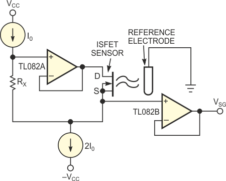 |
| Figure 1. |
This circuit is a classic configuration for biasing ISFET sensors. |
| |
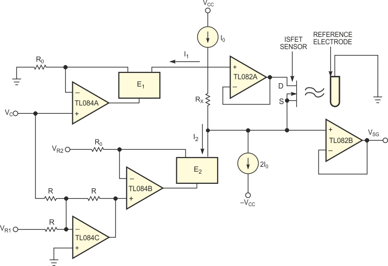 |
| Figure 2. |
This novel floating current source represents an improved way to bias ISFET sensors. |
Figure 3 and Figure 4 show the measured absolute errors occurring in the bias current and voltage, respectively. The main advantages of this current source are that it floats and that you can connect it to any circuit without changing its operating mode, because the currents I1 and I2 are complementary. Therefore, if I1 diminishes, the I2 current increases in the same proportion, and this action does not affect the other currents in the circuit. In the ISFET-sensor case, changing I2 via VC allows you to vary the bias voltage applied to the sensor without changing the bias current, IDS.
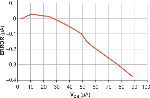 |
| Figure 3. |
Very small measured errors appear in the ISFET’s bias current. |
| |
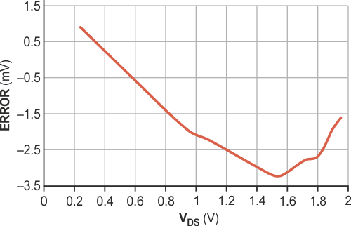 |
| Figure 4. |
Only a few millivolts of error appear over the full range of VDS. |
Materials on the topic
- Datasheet Texas Instruments REF200
- Datasheet Texas Instruments TL082
- Datasheet Texas Instruments TL084